Home/
Registry/
Ford/
Mustang/
2005-2014/
“SHELBY GT500”/
Photo
supermotors.net/registry/media/665582
2001 Ford F-150 A/C Compressor Clutch Wiring Diagram - WOT Relay & PCM Circuit
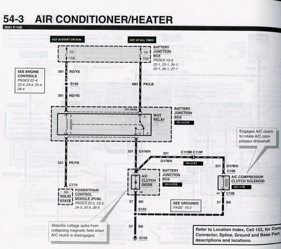
Wiring diagram for a 2001 F-150 A/C and heater system showing the WOT relay, A/C clutch solenoid, PCM and color-coded circuits.
This is page 54-3 of a Ford wiring diagram manual covering the Air Conditioner/Heater system for the 2001 F-150. The diagram traces the A/C compressor clutch control circuit. Power comes from two sources in the Battery Junction Box: fuse 23 (15A, hot in start or run) feeding circuit 391 RD/YE through splice S155, and fuse 13 (15A, hot at all times) feeding circuit 883 PK/LB. Both feed the WOT (wide-open throttle) relay in the Battery Junction Box (connector 151-3 C10), whose coil is controlled by the Powertrain Control Module (PCM, solid state driver, pin 69, via circuit 331 PK/YE and connector C174). The relay output on circuit 321 GY/WH passes through connectors C119M/C119F and C106 to the A/C compressor clutch solenoid (151-1 F8), with a parallel A/C clutch diode in the Battery Junction Box that absorbs the voltage spike when the clutch disengages. The ground path is circuit 57 BK through splice S102 to ground G102 (see Grounds, page 10-3). Callouts explain the clutch solenoid engages the compressor driveshaft, and a note directs readers to Location Index Cell 152 for connector, splice, and ground locations. Cross-references to Engine Controls pages 22-4 through 26-4 and PCM pages 22-5 through 26-5 are included.
This document covers 2001, which may differ from this 2007 Ford Mustang.
Is this accurate? Sign in to help verify it.
Frequently asked questions
- What fuses power the A/C clutch circuit on the 2001 F-150?
- Two 15A fuses in the Battery Junction Box: fuse 23 (hot in start or run, feeding circuit 391 RD/YE) and fuse 13 (hot at all times, feeding circuit 883 PK/LB).
- What wire color feeds the A/C compressor clutch solenoid?
- Circuit 321 GY/WH (gray/white) runs from the WOT relay through connectors C119M/C119F and C106 to the A/C compressor clutch solenoid.
- What controls the WOT relay for the A/C clutch?
- The Powertrain Control Module (PCM) via a solid-state driver on pin 69, using circuit 331 PK/YE through connector C174.
- What is the purpose of the A/C clutch diode?
- It absorbs the voltage spike from the collapsing magnetic field when the A/C clutch is disengaged. It is located in the Battery Junction Box (151-3 C10).
- How is the A/C compressor clutch grounded?
- Through circuit 57 BK, via splice S102, to ground G102 (see Grounds, page 10-3).
Comments
More from this build












No comments yet.