Home/
Registry/
Ford/
Mustang/
2005-2014/
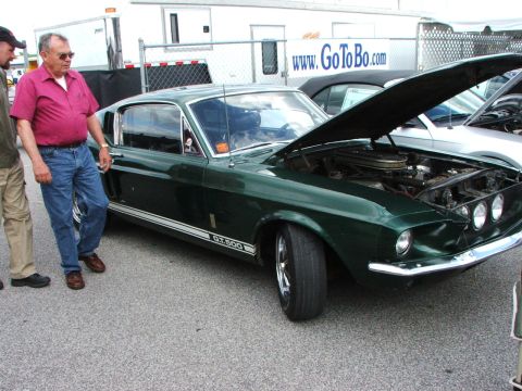
“SHELBY GT500”/
Photo
supermotors.net/registry/media/724092
Ford Left Power Seat Switch Wiring Schematic, Testing & Connector Pinouts

Reference · 2005-2014 MustangAll 41 wiring diagrams
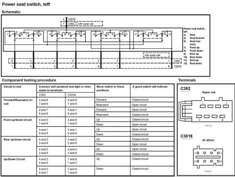

Schematic of the left power seat switch with connector pinout views and a component testing procedure table for circuit continuity.
Part of 2005-2014 Ford Mustang Wiring Diagrams
This document is a service reference page for the left (driver's side) power seat switch on a Ford vehicle, showing a wiring schematic, a component testing procedure, and connector terminal views. The schematic illustrates the internal switch contacts across all positions, with a legend defining each numbered position: 0 (Rest), 5 (Seat forward), 6 (Seat rearward), 7 (Front up), 8 (Front down), 9 (Rear up), 10 (Rear down), 11 (Seat up), and 12 (Seat down). Two connectors are referenced: C352 (used with Super Cab models) and C3016 (all others). The component testing table explains how to check the switch with a self-powered test light or ohmmeter, listing which terminal pairs to probe on each connector, which switch position to select (forward, rearward, up, down), and whether a good switch should show a closed or open circuit for each test, covering the forward/rearward circuit, front up/down circuit, rear up/down circuit, and up/down circuit. Terminal face-view illustrations for connectors C352 (Super Cab, figure F08112) and C3016 (all others, figure F08051) show the pin numbering layout. A technician can use this page to bench-test and diagnose a faulty power seat switch.
Is this accurate? Sign in to help verify it.
Frequently asked questions
- How do I test the left power seat switch forward/rearward circuit?
- Connect a self-powered test light or ohmmeter to terminals 4 and 6 / 7 and 8 (on C352 or C3016). A good switch shows a closed circuit in Forward and an open circuit in Rearward. Then test terminals 4 and 7 / 6 and 8: a good switch shows open in Forward and closed in Rearward.
- What do the switch position numbers mean on the schematic?
- 0 = Rest, 5 = Seat forward, 6 = Seat rearward, 7 = Front up, 8 = Front down, 9 = Rear up, 10 = Rear down, 11 = Seat up, 12 = Seat down.
- Which connector is used for the power seat switch on Super Cab models?
- Connector C352 is used with Super Cab models; connector C3016 is used on all others.
- How is the front up/down circuit tested?
- With the meter on terminals 4 and 5 / 1 and 8, a good switch is closed in Up and open in Down. On terminals 4 and 1 / 5 and 8, it should be open in Up and closed in Down.
- What tool does the testing procedure call for?
- A self-powered test light or an ohmmeter connected to the specified switch terminals.

No comments yet.