Home/
Registry/
Ford/
Bronco/
1992-1996/
1996 Ford Bronco/
Photo
supermotors.net/registry/media/685241
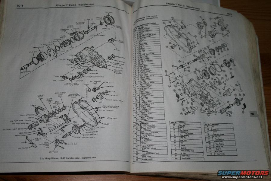
Ford Bronco Borg-Warner 13-45 & 13-56 Transfer Case Exploded View Diagrams
Reference · 1992-1996 BroncoAll 169 exploded parts diagrams















Service manual spread showing exploded views of a Borg-Warner transfer case with numbered parts and legends.
Part of 1992-1996 Ford Bronco Exploded Parts Diagrams
This is a two-page spread from a Haynes-style repair manual, Chapter 7 Part C 'Transfer case' (pages 7C-4 and 7C-5). The left page (7C-4) presents a detailed exploded-view illustration labeled '3.1b Borg-Warner 13-45 transfer case - exploded view,' with dozens of callout labels identifying components such as the planetary gear case, annulus gear, snap rings, needle bearings, front and rear output shafts, oil pump body and covers, drive and driven sprockets, drive chain, shift fork, shift rail, shift cam, speedometer drive gear, four-wheel-drive indicator switch, filler and drain plugs, front output yoke, and various seals, O-rings, and washers. The right page (7C-5) shows an exploded view of the Borg-Warner 13-56 manual-shift transfer case accompanied by a numbered parts legend keyed to the illustration. Legible legend entries include items such as Cover Pump Front, Cam Shift, Hub Reduction, Fork Reduction, Switch 4WD Indicator, Lever Shaft and Pin Assy, Spring Assist, Gear PTO, Yoke Assembly Front, Cover PTO, Case Assy Transfer, and numerous seals, retaining rings, and bearings. A reader can use these pages to identify individual transfer case components and their assembly relationships when disassembling or rebuilding a Borg-Warner 13-45 or 13-56 transfer case.
Is this accurate? Sign in to help verify it.
Frequently asked questions
- What transfer cases are covered on these manual pages?
- The pages show exploded-view diagrams of the Borg-Warner 13-45 transfer case (figure 3.1b, page 7C-4) and the Borg-Warner 13-56 manual transfer case (page 7C-5), from Chapter 7 Part C 'Transfer case.'
- What internal components are labeled in the Borg-Warner 13-45 exploded view?
- Labeled parts include the planetary gear case, annulus gear, snap rings, needle bearings, rear and front output shafts, oil pump body with front and rear covers and wear pads, drive and driven sprockets, drive chain, shift fork, shift rail, shift cam, speedometer drive gear, four-wheel-drive indicator switch, detent ball and spring, filler and drain plugs, front output yoke, seals, O-rings and washers.
- Does the document include a parts legend for the 13-56 transfer case?
- Yes, page 7C-5 includes numbered item/description legend tables keyed to the exploded view, with entries such as 64 Cover Pump Front, 65 Cam Shift, 74 Switch 4WD Indicator, 78 Spring Assist, 90 Gear PTO, 94 Yoke Assembly Front, 101 Cover PTO, and 103 Case Assy Transfer.
- Where are the drain and fill plugs identified on the 13-45 transfer case?
- The exploded view on page 7C-4 has callouts for both a FILLER PLUG and a DRAIN PLUG on the transfer case housing.






No comments yet.