Home/
Registry/
Ford/
Mustang/
2005-2014/
“SHELBY GT500”/
Photo
supermotors.net/registry/media/724096
1997 Ford Fog Lamps Wiring Diagram 086-001 - Fog Lamp Relay & DRL Circuit

Reference · 2005-2014 MustangAll 41 wiring diagrams
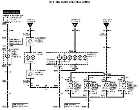
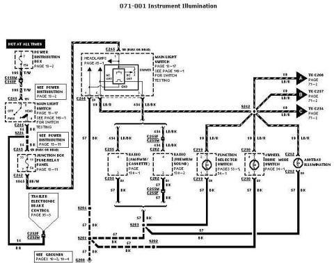
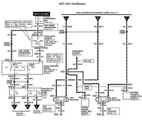
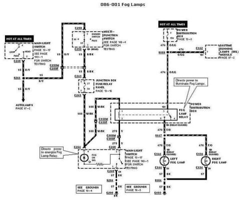
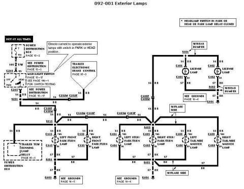
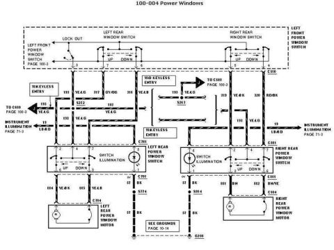
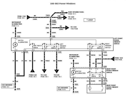
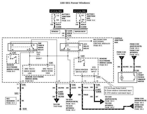









Automotive wiring diagram for the fog lamps showing the fog lamp relay, main light switch and left and right fog lamps with color-coded circuits.
Part of 2005-2014 Ford Mustang Wiring Diagrams
This document is page 086-001, a Ford fog lamp circuit wiring diagram. It shows two 'HOT AT ALL TIMES' power feeds: one through the Main Light Switch (page 13-17) with circuit 15 R/Y feeding the autolamps circuit (page 87-2), and one through fuse 9 (15A) in the Power Distribution Box (page 13-3) via circuit 474 O/LG to the Daytime Running Lamps (DRL) Module (page 97-2) and the Fog Lamp Relay. The Multi-Function (dimmer) Switch feeds circuit 13 R/BK through connectors C253M/C253F to the Junction Box Fuse/Relay Panel (page 13-16) fuse 27 (5A), which outputs circuit 188 W/BK through C158M/C158F, then 275 Y through C160M/C160F to the fog lamp on-indicator and Main Light Switch fog contacts, energizing the Fog Lamp Relay. When the relay closes, circuit 478 T/O feeds splice S147 to the Left Fog Lamp (C144) and Right Fog Lamp (C134). Grounds are via circuit 57 BK: switch/indicator side through S204 to G200 (grounds page 10-4) and lamp side through S104 to G103 (grounds page 10-5). Switch testing references are pages 149-1 and 149-4.
Is this accurate? Sign in to help verify it.
Frequently asked questions
- What fuse powers the fog lamp relay circuit?
- Fuse 9 (15A) in the Power Distribution Box (page 13-3) provides constant power on circuit 474 O/LG to the Fog Lamp Relay and the DRL Module; the control side runs through fuse 27 (5A) in the Junction Box Fuse/Relay Panel (page 13-16).
- What wire color feeds the fog lamps when the relay is closed?
- Circuit 478 T/O (tan/orange) runs from the Fog Lamp Relay through splice S147 to both the left fog lamp (connector C144) and right fog lamp (connector C134).
- Where do the fog lamps get their ground?
- Both fog lamps ground through circuit 57 BK via splice S104 to ground G103 (see grounds page 10-5); the switch/indicator side grounds through S204 to G200 (see grounds page 10-4).
- Which connectors are in the fog lamp control circuit?
- The diagram shows C246 and C244 at the Main Light Switch, C259 at the Multi-Function Switch, C253M/C253F, C243 at the fuse/relay panel, C158M/C158F, C160M/C160F, C142 at the DRL module, and C144/C134 at the fog lamps.
- How do I test the switches in this circuit?
- The diagram directs you to page 149-1 for Main Light Switch testing and page 149-4 for Multi-Function (dimmer) Switch testing.






No comments yet.