Home/
Registry/
Ford/
Mustang/
2005-2014/
“SHELBY GT500”/
Photo
supermotors.net/registry/media/724097
1997 Ford F-150 Headlamp Wiring Diagram 085-001 - Headlights & DRL Circuit

Reference · 2005-2014 MustangAll 41 wiring diagrams
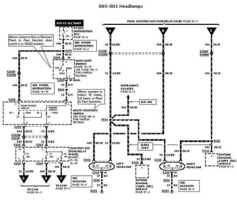
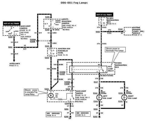
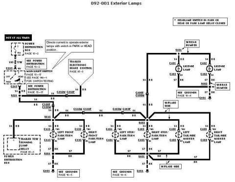
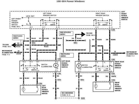
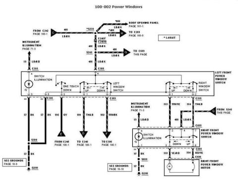









Automotive wiring diagram for the headlamps showing left and right headlamps, the DRL module and color-coded circuits.
Part of 2005-2014 Ford Mustang Wiring Diagrams
This document is page 085-001, "Headlamps," from a Ford factory wiring diagram set. It traces the headlamp circuit from a hot-at-all-times feed in the Power Distribution Box (page 13-2), through splice S212 and connector C246 into the Main Light Switch (page 13-17, switch testing on page 149-1, positions OFF/HEAD/PARK), then via circuit 196 DB/O through connectors C253F/C253M to the Multi-Function Switch (page 149-4), which contains the flash-to-pass and dimmer switches for HI/LO/Flash-to-Pass selection. Output circuits 632 GY/O and 13 R/BK pass through the Junction Box Fuse/Relay Panel (pages 13-4 and 13-16, including a 10A fuse in position 26) and exit as 12 LG/BK, 160 DB/W, and 161 DG/O to connectors C159 and C160 (page 85-1). On the load side, these circuits feed the left headlamp (C143) and right headlamp (C133) high and low beams, with splices S114 and S122, a 932 GY/W feed to the instrument cluster (page 62-6) for non-DRL vehicles, and connections to the Daytime Running Lamps (DRL) module at C142 (page 97-2) on DRL-equipped vehicles. Grounds run via 57 BK wires through S106 to G104 and S104 to G103 (grounds pages 10-5 and 10-6).
Is this accurate? Sign in to help verify it.
Frequently asked questions
- What wire colors feed the headlamps in this diagram?
- Circuit 12 LG/BK (light green/black) is the high beam feed, 160 DB/W (dark blue/white) feeds the left headlamp low beam, and 161 DG/O (dark green/orange) feeds the right headlamp low beam. The switch feed is 196 DB/O.
- What connectors are at the headlamps?
- The left headlamp uses connector C143 and the right headlamp uses connector C133, each with LO and HI terminals and a 57 BK ground wire.
- Where do the headlamp grounds go?
- The left headlamp grounds through 57 BK via splice S106 to G104 (see grounds page 10-6); the right headlamp grounds through 57 BK via splice S104 to G103 (see grounds page 10-5).
- What does the multi-function switch do in this circuit?
- Per the diagram callout, it allows the operator to select HI beam, LO beam, or Flash-to-Pass functions; it contains the flash-to-pass switch and dimmer switch, with switch testing on page 149-4.
- How are Daytime Running Lamps (DRL) connected?
- On DRL-equipped vehicles, circuits 12 LG/BK and 161 DG/O connect through connector C142 to the Daytime Running Lamps (DRL) Module, covered on page 97-2. A 932 GY/W wire to the instrument cluster (page 62-6) applies only without DRL.






No comments yet.