Home/
Registry/
Ford/
Mustang/
2005-2014/
“SHELBY GT500”/
Photo
supermotors.net/registry/media/724098
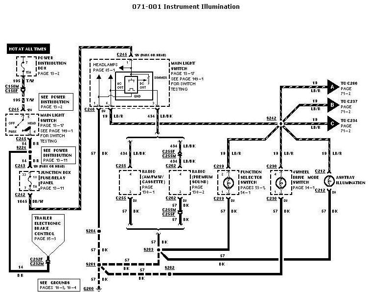
1997 Ford Instrument Illumination Wiring Diagram 071-001 - Dash Light Circuit
Reference · 2005-2014 MustangAll 41 wiring diagrams
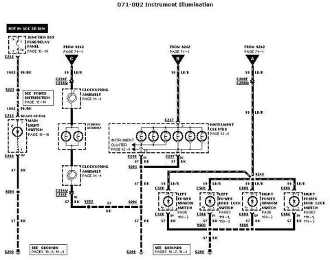
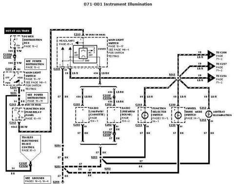
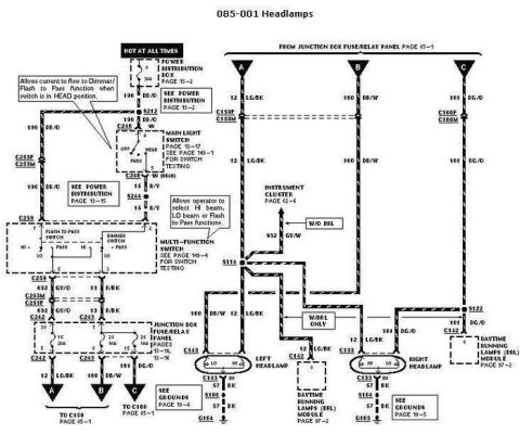
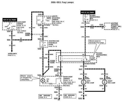
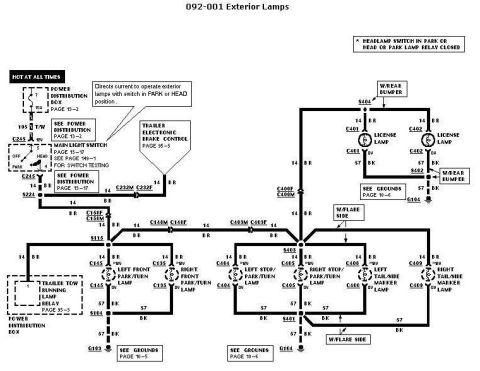









Automotive wiring diagram for instrument illumination showing the main light switch, radio and various illuminated switches with color-coded circuits.
Part of 2005-2014 Ford Mustang Wiring Diagrams
This is page 071-001, "Instrument Illumination," from a Ford factory-style wiring diagram set. It traces the instrument/panel illumination (dimming) circuit from a hot-at-all-times 15A fuse in the power distribution box (page 13-2), through circuit 195 T/W to the main light switch (page 13-17, with switch testing on page 149-1). With the switch in PARK or HEAD, power feeds circuit 14 BR/BU through splice S224 and a 15A fuse (position 7) in the junction box fuse/relay panel (page 13-11), then to the dimmer module (AC OUT/DC OUT/GND) associated with the headlamps circuit (page 85-1). The dimmed output on circuit 19 LB/R distributes via splice S242 to connectors C206, C237, and C234 (page 71-2), and to illumination bulbs in the AM/FM cassette radio (page 150-1), premium sound radio (page 150-2), HVAC function selector switch (pages 53-1, 54-1), 4-wheel drive mode switch (page 34-1), and ashtray illumination. Circuit 434 LB/BK also feeds the radios. All illumination grounds return on circuit 57 BK through splices S204, S203, S201, and S202 to ground G200 (grounds pages 10-3, 10-4). A branch on 1045 DB/W feeds the trailer electronic brake control (page 95-3) via C232F/C232M.
Is this accurate? Sign in to help verify it.
Frequently asked questions
- What fuse powers the instrument illumination circuit in this diagram?
- Power comes from a 15A fuse in the power distribution box (page 13-2, circuit 195 T/W) and then a 15A fuse in position 7 of the junction box fuse/relay panel (page 13-11) after the main light switch.
- What wire color is the dimmed instrument illumination feed?
- Circuit 19 LB/R (light blue/red) carries the dimmed illumination feed from splice S242 to connectors C206, C237, C234 and to the function selector switch, 4WD mode switch, and ashtray illumination. Circuit 434 LB/BK feeds the radios.
- Where do the instrument illumination circuits ground?
- All illumination lamps ground on circuit 57 BK (black) through splices S204, S203, S201, and S202 to ground G200 (see grounds pages 10-3, 10-4).
- Which components receive illumination power in this circuit?
- The AM/FM cassette radio (C255), premium sound radio (C262), HVAC function selector switch (C219), 4-wheel drive mode switch (C230), ashtray illumination (C212), and connectors C206, C237, and C234 on page 71-2.
- Where is the main light switch tested per this diagram?
- The main light switch is shown on page 13-17, and the diagram says to see page 149-1 for switch testing.






No comments yet.