Home/
Registry/
Ford/
Mustang/
2005-2014/
“SHELBY GT500”/
Photo
supermotors.net/registry/media/724099
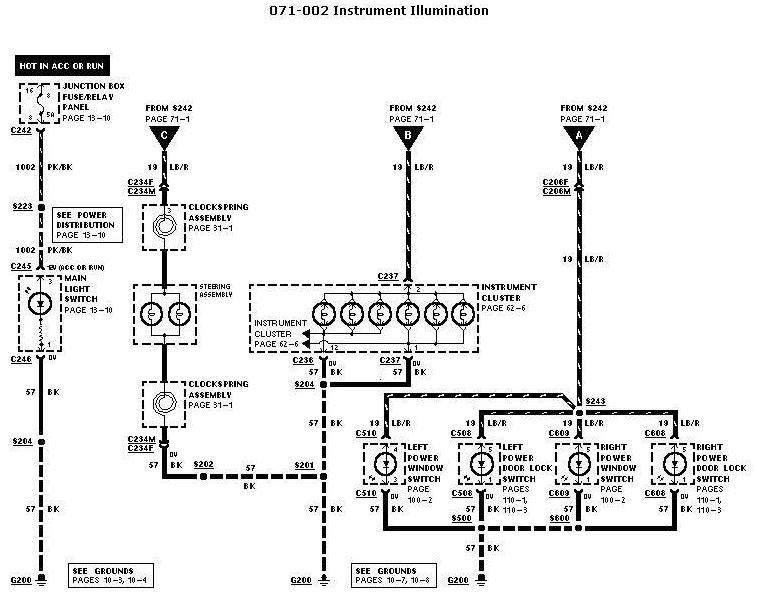
1997 Ford Instrument Illumination Wiring Diagram 071-002 - Dash Light Circuit
Reference · 2005-2014 MustangAll 41 wiring diagrams
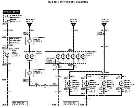
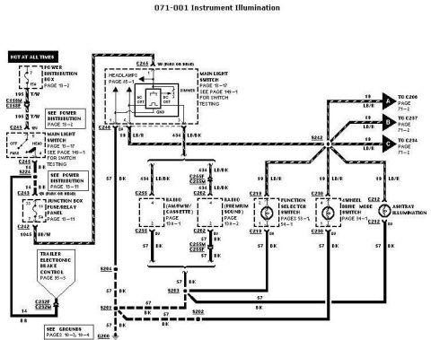
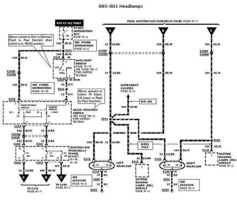
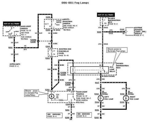









Automotive wiring diagram for instrument illumination showing the clock spring assembly, instrument cluster and power window/door switches with color-coded circuits.
Part of 2005-2014 Ford Mustang Wiring Diagrams
This is a Ford factory-style wiring diagram, circuit sheet 071-002 "Instrument Illumination." It shows the instrument/dash illumination lighting circuit fed from fuse 8 (5A) in the junction box fuse/relay panel (Hot in ACC or Run), through circuit 1002 (PK/BK wire) to the main light switch (dimmer), then out on circuit 19 (LB/R, light blue/red) via splice S242 to three branches: (C) the steering-wheel illumination bulbs through the clockspring assembly connectors C234F/C234M; (B) the instrument cluster illumination bulbs via connectors C236/C237; and (A) via connectors C208F/C208M and splice S243 to the left and right power window switches (C510, C609) and left and right power door lock switches (C508, C608) for switch backlighting. All grounds return on circuit 57 (BK wire) through splices S201, S202, S204, S243, S500, S600 to grounds G200. Page cross-references are given for power distribution (13-10), clockspring (31-1), instrument cluster (62-6), power windows (100-2), power door locks (110-1, 110-3), and grounds (10-3, 10-4, 10-7, 10-8). The filename indicates it is part 2 of a 1997 instrument lights diagram set.
Is this accurate? Sign in to help verify it.
Frequently asked questions
- What fuse powers the instrument illumination circuit in this diagram?
- Fuse 8, a 5A fuse in the junction box fuse/relay panel (page 13-10), which is hot in ACC or RUN.
- What wire colors are used for the instrument illumination circuit?
- Circuit 1002 is PK/BK (pink/black) from the fuse panel to the main light switch, circuit 19 is LB/R (light blue/red) for the illumination feed, and circuit 57 is BK (black) for ground.
- Which switches receive illumination power from splice S243?
- The left power window switch (C510), left power door lock switch (C508), right power window switch (C609), and right power door lock switch (C608).
- What connectors are used at the clockspring assembly?
- Connectors C234F and C234M, shown feeding the steering assembly illumination bulbs (clockspring on page 31-1).
- Where does the illumination circuit ground?
- Through circuit 57 (BK) via splices S201, S202, S204, S500 and S600 to grounds G200; grounds are detailed on pages 10-3, 10-4, 10-7, and 10-8.






No comments yet.