Home/
Registry/
Ford/
Mustang/
2005-2014/
“SHELBY GT500”/
Photo
supermotors.net/registry/media/724101
1997 Ford F-150 Turn/Stop/Hazard Lamps Wiring Diagram 090-003 (BOO Switch)

Reference · 2005-2014 MustangAll 41 wiring diagrams
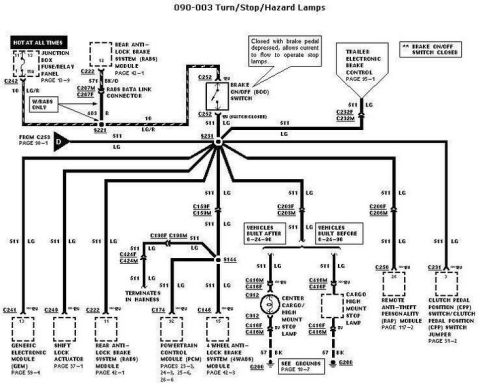
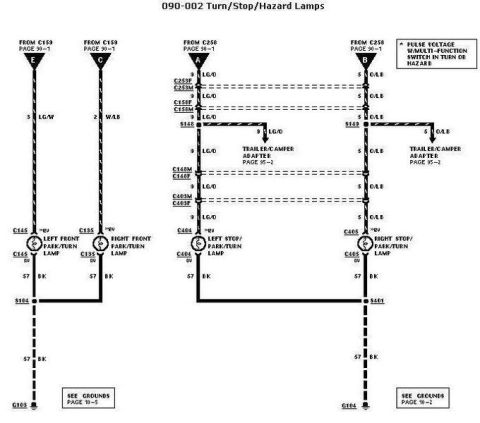
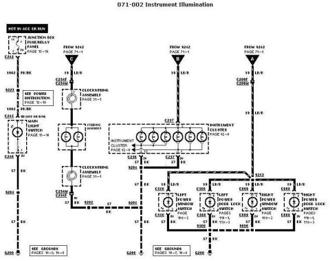
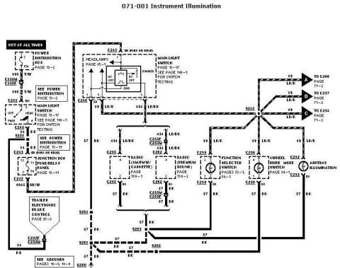
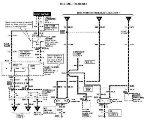
Automotive wiring diagram for turn, stop and hazard lamps showing the brake on/off switch, control modules and high mount stop lamp with color-coded circuits.
Part of 2005-2014 Ford Mustang Wiring Diagrams
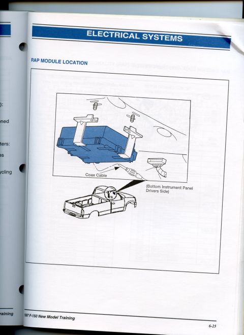
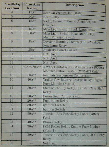
This is page 090-003, "Turn/Stop/Hazard Lamps," from a Ford factory wiring diagram set. It traces the brake lamp circuit from a 15A fuse (position 13) in the Junction Box Fuse/Relay Panel through the Brake On/Off (BOO) switch, which closes with brake pedal depression to power circuit 511 (light green, LG) at splice S231. From there the 511 LG circuit branches to numerous components: the Trailer Electronic Brake Control (via C232F/C232M), the center cargo/high-mount stop lamp (with different connectors and lamps for vehicles built before vs. after 6-24-96, grounding at G200 via circuit 57 BK), the Remote Anti-theft Personality (RAP) Module, the Clutch Pedal Position (CPP) switch/jumper, the Generic Electronic Module (GEM), the Shift Lock Actuator, the Rear Anti-Lock Brake System (RABS) module, the Powertrain Control Module (PCM), and the 4-Wheel Anti-Lock Brake System (4WABS) module. It also shows the RABS data link connector wiring (circuits 571 BK/O and 483 R) and connectors such as C159, C198, C203, C206, C416, and C424. Readers can learn the wire colors, circuit numbers, connector IDs, splice points, and cross-referenced diagram pages for the stop lamp circuit.
This document covers 1996-1997, which may differ from this 2007 Ford Mustang.
Is this accurate? Sign in to help verify it.
Frequently asked questions
- What fuse powers the stop lamp circuit in this diagram?
- A 15A fuse in position 13 of the Junction Box Fuse/Relay Panel (Page 13-9), hot at all times, feeding circuit 10 LG/R to the Brake On/Off switch.
- What wire color is the main stop lamp feed after the brake switch?
- Circuit 511, light green (LG), which distributes from splice S231 to the stop lamps, trailer brake control, GEM, PCM, RABS, 4WABS, RAP module, and other components.
- How does the high-mount stop lamp wiring differ by build date?
- Vehicles built after 6-24-96 use a Center Cargo/High Mount Stop Lamp through connectors C416M/C416F and C912; vehicles built before 6-24-96 use a Cargo High Mount Stop Lamp through C416M/C416F. Both ground on circuit 57 BK at G200.
- What does the Brake On/Off (BOO) switch do?
- Per the diagram note, it closes when the brake pedal is depressed, allowing current to flow to operate the stop lamps.
- Which modules receive the 511 LG brake signal?
- The Trailer Electronic Brake Control, Remote Anti-theft Personality (RAP) Module, Generic Electronic Module (GEM), Shift Lock Actuator, RABS module, Powertrain Control Module (PCM), 4WABS module, and the Clutch Pedal Position (CPP) switch/jumper.
No comments yet.