Home/
Registry/
Ford/
Mustang/
2005-2014/
“SHELBY GT500”/
Photo
supermotors.net/registry/media/724110
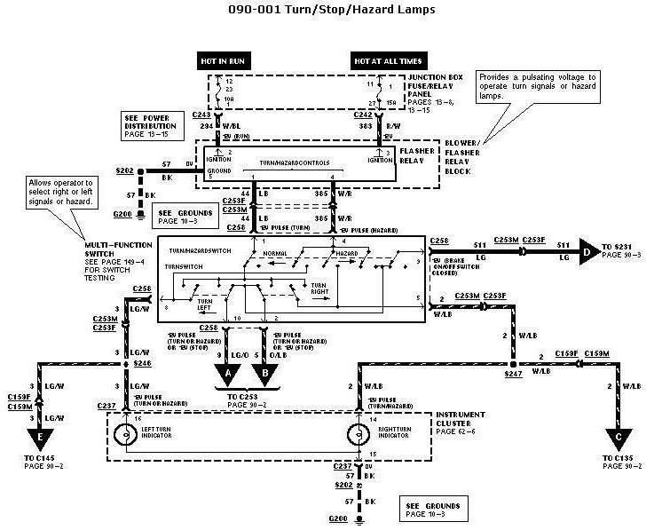
Ford Turn/Stop/Hazard Lamps Wiring Diagram 090-001 - Flasher & Multi-Function Switch
Reference · 2005-2014 MustangAll 41 wiring diagrams
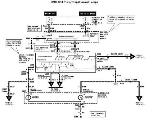
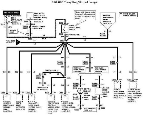
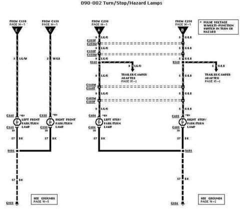
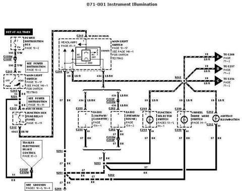









Automotive wiring diagram for turn, stop and hazard lamps showing the multifunction switch, flasher relay and turn indicators with color-coded circuits.
Part of 2005-2014 Ford Mustang Wiring Diagrams
This document is page 090-001 of a Ford factory wiring diagram covering the Turn/Stop/Hazard Lamps circuit. It traces power from two junction box fuse/relay panel feeds, one hot in RUN and one hot at all times (including a 15A fuse position 27/12), through connectors C243 (circuit 294 W/BL) and C242 (circuit 383 R/W) to the blower/flasher relay block, which provides the pulsating voltage that operates the turn signals and hazard lamps. Output circuits 44 (LB) and 385 (W/R) pass through connectors C253F/C253M and C258 to the multi-function switch, which contains the turn/hazard switch (NORMAL/HAZARD) and the turn switch (TURN LEFT/TURN RIGHT). Switch outputs feed circuit 511 (LG) toward S231, circuit 2 (W/LB) via S247 and C159F/C159M to C135 (right side), circuit 3 (LG/W) via S246 to C145 (left side), and circuits 9 (LG) and 5 (O/LB) to C253 for the rear stop/turn lamps. The instrument cluster left and right turn indicators (connector C237, pins 18 and 14) and grounds through splice S202 to G200 are also shown. Cross-references point to power distribution (page 13-15), grounds (page 10-3), switch testing (page 149-4), and continuation pages 90-2, 90-3, and 62-6.
Is this accurate? Sign in to help verify it.
Frequently asked questions
- What provides the flashing voltage for the turn signals and hazard lamps?
- The blower/flasher relay block, which the diagram notes 'provides a pulsating voltage to operate turn signals or hazard lamps.' It is fed by a hot-in-RUN circuit (294 W/BL through C243) and a hot-at-all-times circuit (383 R/W through C242) from the junction box fuse/relay panel.
- What wire colors are used for the turn/hazard circuits in this diagram?
- Circuit 44 is light blue (LB), circuit 385 is white/red (W/R), circuit 3 is light green/white (LG/W) for the left side, circuit 2 is white/light blue (W/LB) for the right side, circuit 511 is light green (LG), circuit 9 is LG and circuit 5 is O/LB to the rear via C253, and ground circuit 57 is black (BK).
- Which connector and pins serve the instrument cluster turn indicators?
- Connector C237 on the instrument cluster: pin 18 (3 LG/W) for the left turn indicator, pin 14 (2 W/LB) for the right turn indicator, and pin 8 (57 BK) for ground through splice S202 to G200.
- Where does the diagram say to look for multi-function switch testing?
- The multi-function switch note says 'SEE PAGE 149-4 FOR SWITCH TESTING.' The switch includes the turn/hazard switch (NORMAL/HAZARD) and turn switch (TURN LEFT/TURN RIGHT).
- Where are the grounds for this circuit?
- Ground circuit 57 (BK) runs through splice S202 to ground G200; the diagram references 'SEE GROUNDS PAGE 10-3' in two places.






No comments yet.