Home/
Registry/
Ford/
Mustang/
2005-2014/
“SHELBY GT500”/
Photo
supermotors.net/registry/media/773750
DryAire Compressed Air Piping Layout Diagram - Shop Air Line & Dryer Setup

Reference · 2005-2014 MustangAll 19 schematics

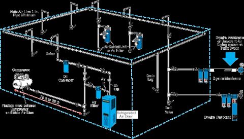
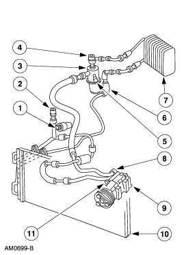
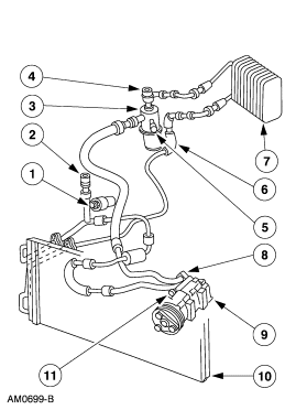
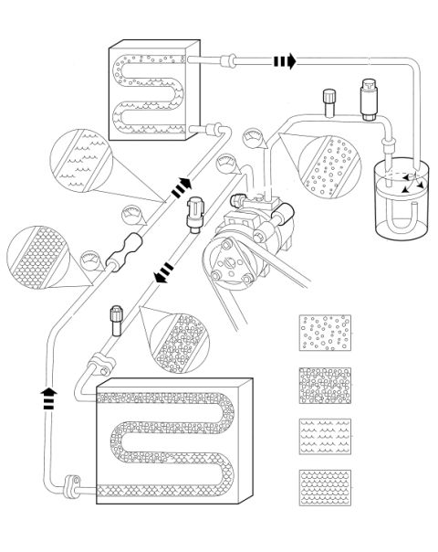









Schematic of a shop compressed-air piping layout showing compressor, coalescer, refrigerated dryer, filters and dryaire desiccant components.
Part of 2005-2014 Ford Mustang Schematics
This document is a schematic diagram of a compressed air supply piping layout for a shop, typically used to supply clean, dry air to a paint booth. It illustrates a complete air distribution system beginning at the compressor, which connects to the main air line via a 15 ft to 20 ft flexible hose. The main air line is specified as a minimum of 1-inch pipe and is shown routed in a loop around the shop ceiling with multiple drop legs. Key components are labeled along the air path: a union, an oil coalescer, an air filter, a refrigerated air dryer (with 'Air In' and 'Air Out' points), air control units or air filters at drops, drain legs, and ball valves. At the paint booth location, the diagram highlights the installation of a Dryaire Membrane or Dryaire Desiccant air drying system for final-stage air drying, with both membrane and desiccant configurations illustrated. The drawing shows recommended placement of drops, drains, and filtration equipment to deliver contaminant-free air. This is shop equipment reference material rather than a vehicle-specific wiring or repair diagram, so it applies generically to any garage or refinishing setup, including one servicing the uploader's 2007 Ford Mustang.
Is this accurate? Sign in to help verify it.
Frequently asked questions
- What is the minimum pipe size for the main air line in this layout?
- The diagram specifies the main air line should be 1 in. pipe minimum.
- How long should the flexible hose between the compressor and main air line be?
- The diagram shows a flexible hose of 15 ft to 20 ft between the compressor and the main air line.
- What air drying options are shown at the paint booth?
- The diagram shows a Dryaire Membrane or Desiccant air drying system installed at the paint booth, with both Dryaire Membrane and Dryaire Desiccant units illustrated.
- What components are placed in line between the compressor and the air outlets?
- The layout shows a union, oil coalescer, air filter, refrigerated air dryer (with Air In and Air Out), air control unit or air filter at drops, drain legs, and ball valves.
- Where should drain legs and ball valves be located?
- The diagram shows drain legs at the bottom of vertical drops from the main air line, with ball valves installed on the drops feeding equipment such as the Dryaire units.






No comments yet.