Home/
Registry/
Ford/
Bronco/
1978-1979/
“buyers guide”/
Photo
supermotors.net/registry/media/775696
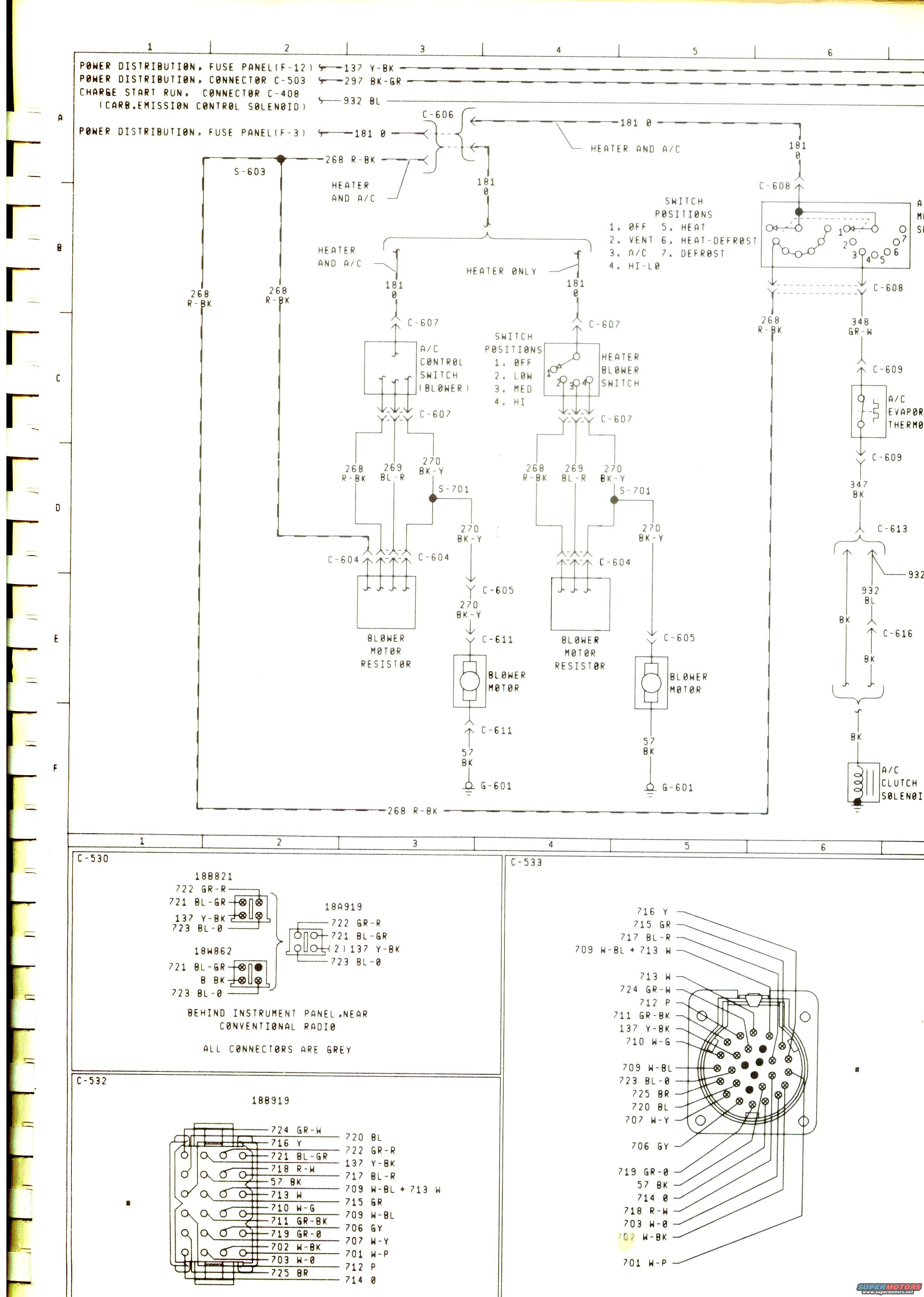
1979 Ford Bronco Heater & A/C Blower Wiring Diagram - Circuits & Connector Pinouts
Reference · 1978-1979 BroncoAll 116 wiring diagrams
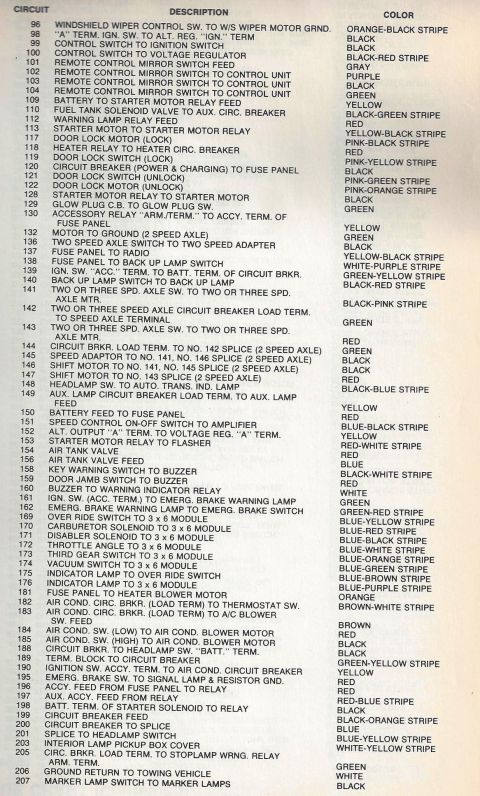
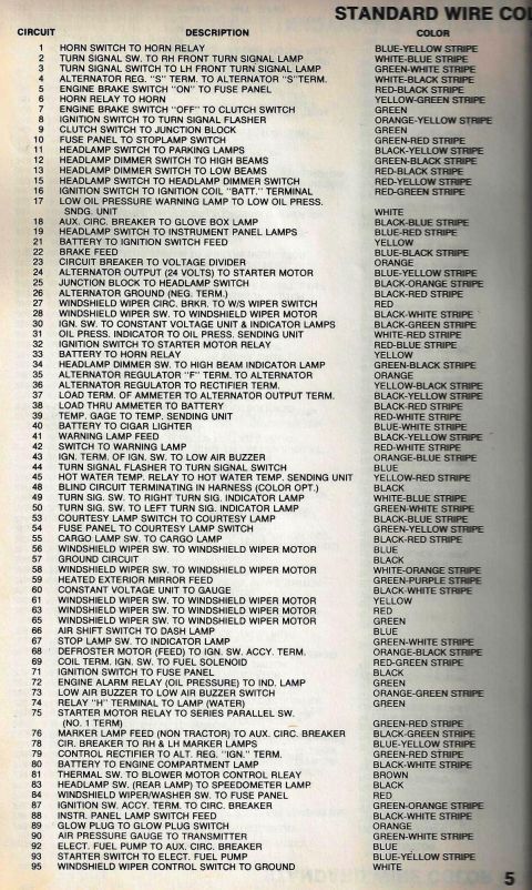
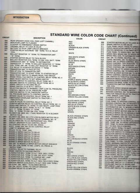
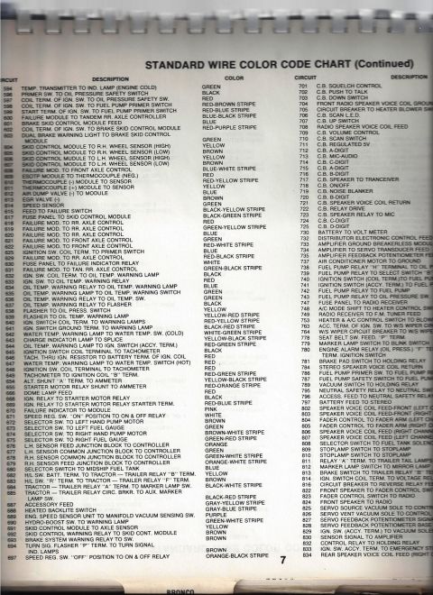
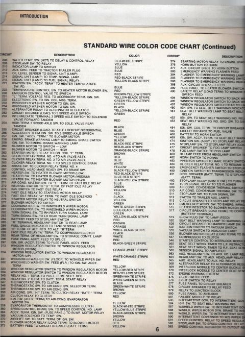
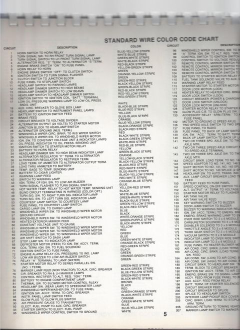
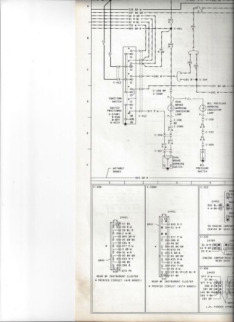
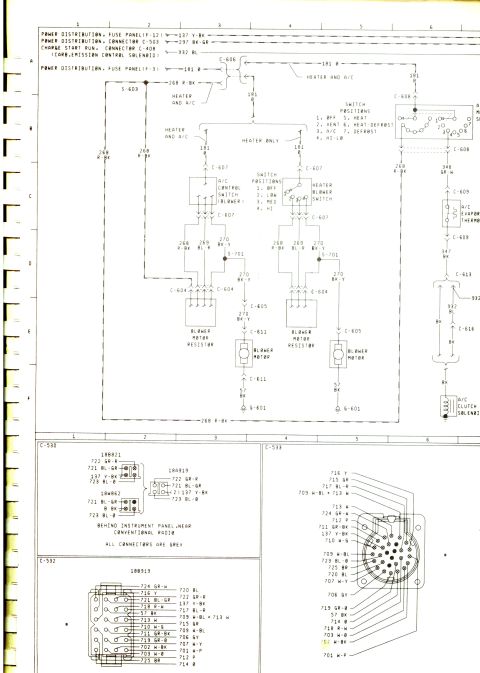
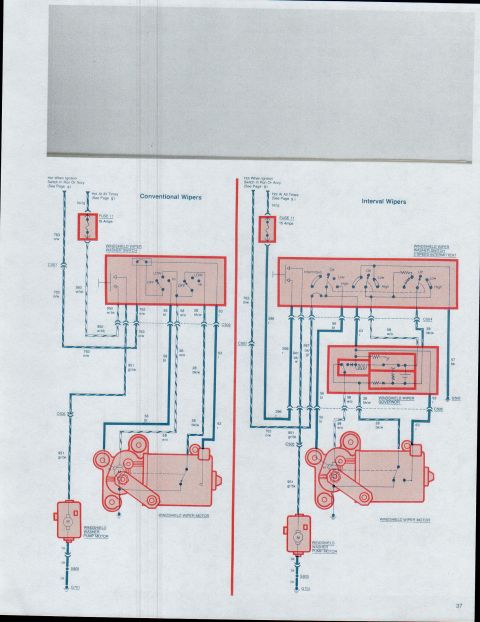
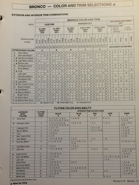
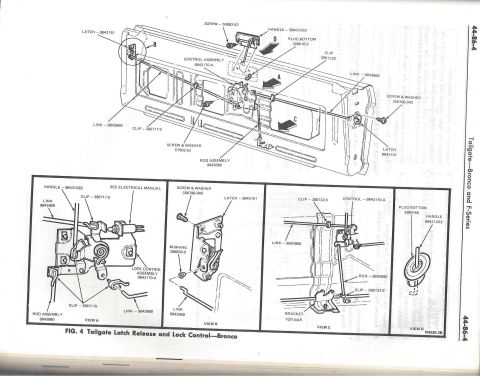


Factory wiring diagram for the heater/AC blower-motor circuit: power distribution fuse panels, blower switch positions, blower motor resistors, A/C clutch solenoid, with connector C-590/C-533/C-580 pinout views.
Part of 1978-1979 Ford Bronco Wiring Diagrams
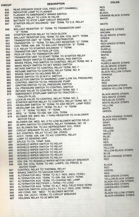
This document is a scanned Ford factory-style wiring diagram page covering the heater and air conditioning (A/C) blower circuits. The top schematic traces power from the fuse panel (F-12 via circuit 137 Y-BK, F-3 via circuit 181 O), connector C-503 (297 BK-GR), and connector C-408 (932 BL, carburetor emission control solenoid) through connectors C-606, C-607, C-608, C-609, C-611, C-613, and C-616. It shows two parallel blower circuits, one for 'Heater and A/C' and one for 'Heater Only', each with a blower switch (positions: Off, Low, Med, Hi), blower motor resistor, blower motor, and ground G-601 via circuit 57 BK. A 7-position mode switch is documented (Off, Vent, A/C, Hi-Lo, Heat, Heat-Defrost, Defrost). The A/C side includes the evaporator thermostat and A/C clutch solenoid (circuits 348 GR-W, 347 BK, 932 BL). Wire circuit numbers and colors are given throughout (e.g., 268 R-BK, 269 BL-R, 270 BK-Y). The lower half provides pinout views of instrument-panel connectors C-530 (parts 18B821, 18A919, 18W862, located behind the instrument panel near the conventional radio, all grey), C-532 (18B919), and C-533, listing each pin's circuit number and wire color.
Is this accurate? Sign in to help verify it.
Frequently asked questions
- What wire feeds the heater/A-C blower circuit from the fuse panel?
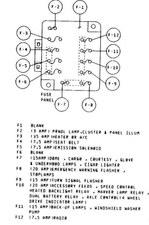
- Circuit 181 O comes from fuse panel position F-3, and circuit 137 Y-BK comes from fuse panel position F-12. Circuit 181 O feeds the blower switches through connector C-606.
- What are the blower switch positions?
- Both the A/C control switch (blower) and the heater blower switch have four positions: 1. OFF, 2. LOW, 3. MED, 4. HI.
- What are the mode switch positions shown?
- 1. OFF, 2. VENT, 3. A/C, 4. HI-LO, 5. HEAT, 6. HEAT-DEFROST, 7. DEFROST.
- How does the blower motor ground?
- The blower motor grounds through circuit 57 BK to ground point G-601 (via connector C-611 on the heater/A-C circuit and C-605 on the heater-only circuit).
- Where is connector C-530 located and what color is it?
- C-530 is located behind the instrument panel, near the conventional radio, and the diagram notes that all connectors there are grey. It involves parts 18B821, 18A919, and 18W862.
- What wire colors go through the blower motor resistor circuits?
- From the blower switch, circuits 268 R-BK, 269 BL-R, and 270 BK-Y run through connector C-604 to the blower motor resistor; 270 BK-Y continues to the blower motor.






No comments yet.