Home/
Registry/
Ford/
Mustang/
2005-2014/
“SHELBY GT500”/
Photo
supermotors.net/registry/media/792862
Ford PCM Power & Ground Wiring Diagram - Relay, Fuses, CHT & IAT Sensors

Reference · 2005-2014 MustangAll 41 wiring diagrams

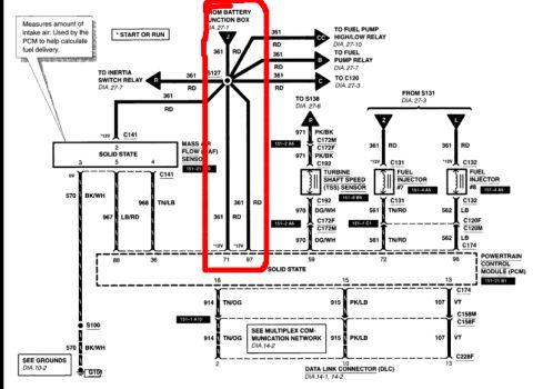
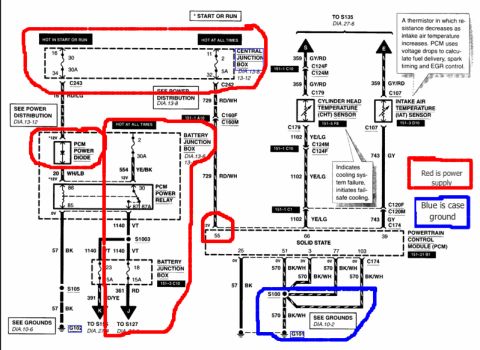









Annotated wiring diagram showing PCM power, junction box distribution and grounds with color-highlighted power and ground paths.
Part of 2005-2014 Ford Mustang Wiring Diagrams
This is a scanned Ford wiring diagram page (annotated by the uploader) showing the power supply and ground circuits for the Powertrain Control Module (PCM). Power sources highlighted in red include: a Central Junction Box fuse (position 16, 30A, hot in start or run; and position 11, 5A, hot at all times) feeding circuit 16 RD/LG and 729 RD/WH; a Battery Junction Box fuse (position 2, 30A) feeding 554 YE/BK; a PCM Power Diode with 20 WH/LB; and a PCM Power Relay (pins 30/85/86/87/87A) providing 1140 VT to splice S1003 and onward through Battery Junction Box fuses 23 (5A) and 18 (15A) to circuits 391 and 361 RD. Grounds highlighted in blue show PCM pins 25, 51, 3, 77, and 103 tied through 57 BK and 570 BK/WH wires to splice S100 and ground G101 (see Grounds DIA.10-2), with a separate ground path through S105 to G102 (DIA.10-6). The diagram also includes the Cylinder Head Temperature (CHT) sensor (359 GY/RD signal, 1102 YE/LG return through C179/C124) and Intake Air Temperature (IAT) sensor (359 GY/RD, 743 GY through C107/C120), with notes explaining the CHT fail-safe cooling function and the IAT thermistor operation. Connector references include C243, C242, C160F/C160M, C124F/C124M, C179, C107, C120F/C120M, and C174.
Is this accurate? Sign in to help verify it.
Frequently asked questions
- Which fuses supply power to the PCM in this diagram?
- Central Junction Box fuse position 16 (30A, hot in start or run) and position 11 (5A, hot at all times), plus Battery Junction Box fuse position 2 (30A). Downstream of the PCM power relay, Battery Junction Box fuses 23 (5A) and 18 (15A) feed circuits 391 and 361 RD.
- What wire colors are used for the PCM power circuits?
- 16 RD/LG, 729 RD/WH, 554 YE/BK, 20 WH/LB, 1140 VT, and 361 RD are shown as power-side circuits; the uploader marked the power supply paths in red.
- Where does the PCM get its ground in this diagram?
- PCM pins 25, 51, 3, 77 and 103 ground through 57 BK and 570 BK/WH wires via splice S100 to ground G101 (see Grounds DIA.10-2); another ground goes through S105 to G102 (DIA.10-6). The uploader marked these in blue as case ground.
- What does the note say about the CHT sensor?
- The callout states it 'Indicates cooling system failure, initiates fail-safe cooling.' The CHT sensor uses circuits 359 GY/RD and 1102 YE/LG through connector C179.
- How does the IAT sensor work according to this diagram?
- It is 'a thermistor in which resistance decreases as intake air temperature increases. PCM uses voltage drops to calculate fuel delivery, spark timing and EGR control.' It connects via C107 with 359 GY/RD and 743 GY wires.






No comments yet.