Home/
Registry/
Ford/
Mustang/
2005-2014/
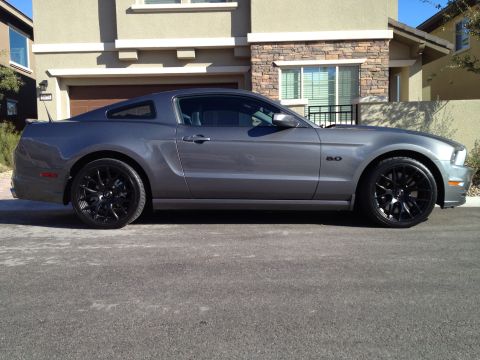
“SHELBY GT500”/
Photo
supermotors.net/registry/media/724114
1998 Ford F-150 Headlamp Wiring Diagram 085-001 - DRL, Dimmer & Fuse Circuits

Automotive wiring diagram for the headlamps showing the main light switch, left and right headlamps and DRL module with color-coded circuits.
This document is page 085-001, "Headlamps," from a Ford wiring diagram manual (EVTM-style). It shows the complete headlamp circuit: power originates from a 20A fuse (position 8) in the Power Distribution Box (hot at all times), feeds through circuit 196 DB/O to the Main Light Switch (OFF/PARK/HEAD positions, switch testing on page 149-1), then via circuit 15 R/V to the Multi-Function Switch containing the dimmer and flash-to-pass functions (testing on page 149-4). Output circuits 632 GV/O and 13 R/BK pass through connectors C253, C259, C242 and C243 to the Junction Box Fuse/Relay Panel (pages 13-10, 13-15) containing two 20A fuses (positions 1C and 5/2C). From there, circuit 12 LG/BK (low beam), 160 DB/W, and 161 DG/O (high beam) route through connectors C159 and C160 to the left headlamp (C143) and right headlamp (C133). The diagram distinguishes wiring with and without Daytime Running Lamps (DRL module, page 97-2), shows circuit 932 GY/W to the instrument cluster (page 62-6), and grounds via 57 BK wires through splices S106/S104 to grounds G104 and G103 (grounds pages 10-5, 10-6). Splices S212, S244, S114, and S122 are identified.
Is this accurate? Sign in to help verify it.
Frequently asked questions
- What fuse powers the headlamp circuit in this diagram?
- Power comes from a 20A fuse (position 8) in the Power Distribution Box, which is hot at all times (Power Distribution Box shown on page 13-2). Two additional 20A fuses (positions 1C and 2C/5) are in the Junction Box Fuse/Relay Panel (pages 13-10 and 13-15).
- What wire colors feed the headlamps?
- Circuit 12 LG/BK (light green/black) feeds the low beams, circuit 160 DB/W (dark blue/white) and circuit 161 DG/O (dark green/orange) feed the high beam side, and circuit 196 DB/O feeds the main light switch. Grounds are circuit 57 BK (black).
- Which connectors serve the left and right headlamps?
- The left headlamp uses connector C143 and grounds through splice S106 to G104; the right headlamp uses connector C133 and grounds through splice S104 to G103.
- Where is switch testing information for the headlamp switches?
- Main light switch testing is on page 149-1 and multi-function switch (dimmer/flash-to-pass) testing is on page 149-4.
- How does this diagram handle Daytime Running Lamps (DRL)?
- It shows branches marked 'W/O DRL' and 'W/DRL ONLY.' Vehicles with DRL route circuits through the Daytime Running Lamps (DRL) Module, referenced on page 97-2, with circuit 932 GY/W going to the instrument cluster (page 62-6).
Comments
More from this build





No comments yet.