Home/
Registry/
Ford/
Mustang/
2005-2014/
“SHELBY GT500”/
Photo
supermotors.net/registry/media/724111
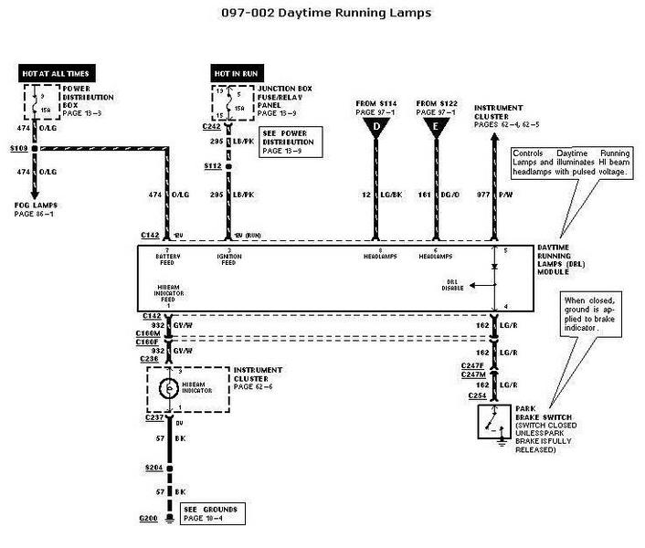
1998 Ford Daytime Running Lamps (DRL) Wiring Diagram - Module & Circuits
Reference · 2005-2014 MustangAll 41 wiring diagrams
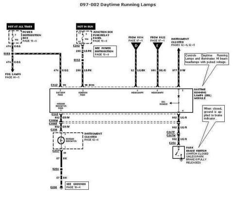
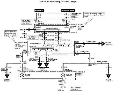
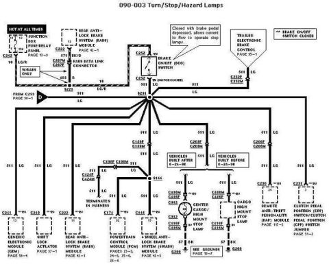
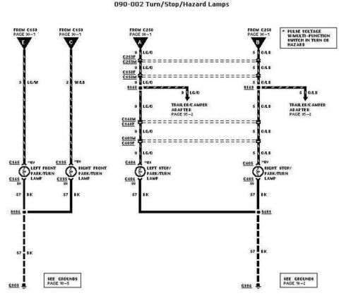









Automotive wiring diagram for daytime running lamps showing the DRL module, headlamps and park brake switch with color-coded circuits.
Part of 2005-2014 Ford Mustang Wiring Diagrams
This document is a Ford factory-style wiring diagram, section 097-002, for the Daytime Running Lamps (DRL) system. It shows the DRL module and all of its circuit connections. Battery power (hot at all times) comes from fuse 9 (15A) in the Power Distribution Box (page 13-3) on circuit 474 O/LG, which also feeds the fog lamps (page 86-1). Ignition (hot in run) power comes from a 15A fuse in the Junction Box Fuse/Relay Panel (page 13-9) via connector C242 on circuit 295 LB/PK. Headlamp circuits 12 LG/BK and 161 DG/O arrive from splices S114 and S122 (page 97-1), and circuit 977 P/W connects to the instrument cluster (pages 62-4, 62-5). The DRL module output on 332 GY/W runs through connectors C160M/C160F and C236 to the high-beam indicator in the instrument cluster (page 62-6), then to ground G200 through circuit 57 BK and splice S204. Circuit 162 LG/R runs through C247F/C247M and C254 to the park brake switch, which is closed unless the park brake is fully released; when closed it applies ground to the brake indicator and disables the DRL function. Notes explain the module pulses voltage to the high beams for DRL operation.
Is this accurate? Sign in to help verify it.
Frequently asked questions
- How does the DRL module make the daytime running lamps work?
- Per the diagram note, the DRL module controls the Daytime Running Lamps and illuminates the HI beam headlamps with pulsed voltage.
- Where does the DRL module get battery power?
- From fuse 9 (15A) in the Power Distribution Box (page 13-3), through splice S109 on circuit 474 O/LG, which also feeds the fog lamps (page 86-1).
- Where does the DRL module get ignition (run) power?
- From a 15A fuse in the Junction Box Fuse/Relay Panel (page 13-9), through connector C242 and splice S112 on circuit 295 LB/PK.
- What does the park brake switch do in the DRL circuit?
- The park brake switch (at connector C254 on circuit 162 LG/R) is closed unless the park brake is fully released; when closed, ground is applied to the brake indicator, which triggers the DRL disable function in the module.
- What wire circuit feeds the high beam indicator in the instrument cluster?
- Circuit 332 GY/W from the DRL module runs through connectors C160M/C160F and C236 to the high beam indicator (instrument cluster, page 62-6), then to ground G200 via circuit 57 BK and splice S204.






No comments yet.