Home/
Registry/
Ford/
Mustang/
2005-2014/
“SHELBY GT500”/
Photo
supermotors.net/registry/media/724115
1998 Ford Daytime Running Lamps Wiring Diagram 097-001 - Headlamp Circuit

Reference · 2005-2014 MustangAll 41 wiring diagrams
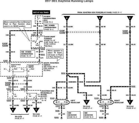
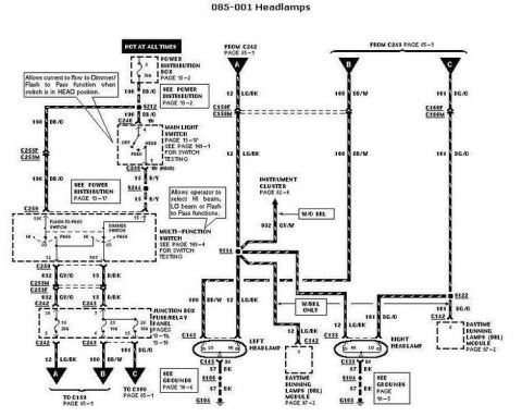
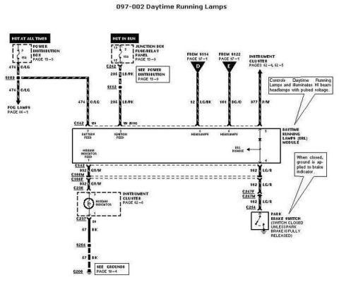
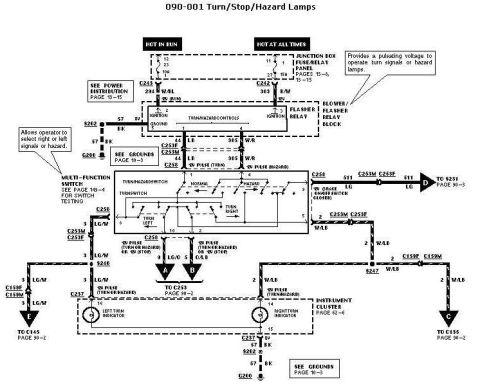
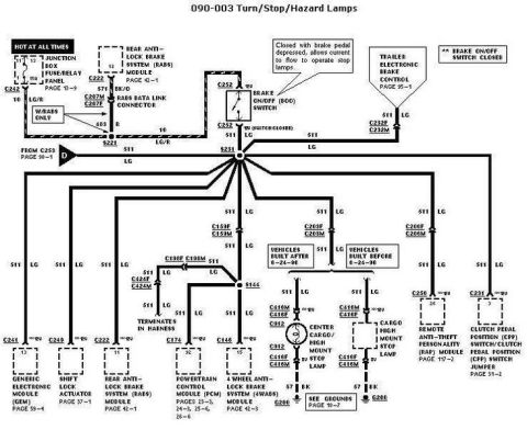









Automotive wiring diagram for daytime running lamps showing the fuse/relay panel, main light switch and left and right headlamps with color-coded circuits.
Part of 2005-2014 Ford Mustang Wiring Diagrams
This document is page 097-001, "Daytime Running Lamps," from a Ford electrical/vacuum troubleshooting manual (EVTM). It is a wiring diagram tracing the headlamp and daytime running lamp circuits from a hot-at-all-times feed through the Power Distribution Box (page 13-2), the Main Light Switch (page 13-17, switch testing page 149-1), and the Multi-Function Switch containing the Flash-to-Pass and Dimmer switches (testing page 149-4). Power then routes through the Junction Box Fuse/Relay Panel (pages 13-15/13-16, showing 20A and 10A fuses) to the left and right headlamps via connectors C159, C160, C143, and C133. Wire circuits identified include 196 DB/O (dark blue/orange), 15 R/Y, 632 GV/O, 13 R/BK, 12 LG/BK (light green/black), 160 DB/W (dark blue/white), 161 DG/O (dark green/orange), and 57 BK ground wires terminating at grounds G103 and G104 (grounds pages 10-5 and 10-6). Splices S212, S244, S114, S122, S104, and S106 are shown. Callout notes explain that the HEAD switch position allows current to the Dimmer/Flash-to-Pass function and that the multi-function switch lets the operator select HI beam, LO beam, or Flash-to-Pass. A reader can trace headlamp power flow, identify wire colors and connector numbers, and find cross-referenced manual pages for testing.
Is this accurate? Sign in to help verify it.
Frequently asked questions
- What wire colors feed the headlamps in this daytime running lamps diagram?
- Circuit 12 LG/BK (light green/black) and 160 DB/W (dark blue/white) feed the left headlamp through connector C143, while 12 LG/BK and 161 DG/O (dark green/orange) feed the right headlamp through connector C133. Ground is circuit 57 BK.
- Where do the headlamps ground in this diagram?
- The left headlamp grounds through splice S106 to ground G104 (see Grounds page 10-6), and the right headlamp grounds through splice S104 to ground G103 (see Grounds page 10-5), both on circuit 57 BK.
- What does the Main Light Switch do in the HEAD position?
- Per the callout, the Main Light Switch (page 13-17) in the HEAD position allows current to flow to the Dimmer/Flash-to-Pass function of the multi-function switch.
- Which pages cover switch testing for this circuit?
- The diagram references page 149-1 for Main Light Switch testing and page 149-4 for Multi-Function Switch (dimmer/flash-to-pass) testing.
- What fuses are involved in the daytime running lamps circuit?
- The diagram shows a 30A fuse in the Power Distribution Box (page 13-2) and fuses in the Junction Box Fuse/Relay Panel (pages 13-15/13-16) including a 20A fuse (position 16) and 10A fuses (positions shown as 2 and 26; some markings partially legible).






No comments yet.