Home/
Registry/
Ford/
Mustang/
2005-2014/
“SHELBY GT500”/
Photo
supermotors.net/registry/media/792863
Ford PCM Power & Ground Wiring Diagram - MAF, TSS, Injectors 7-8, DLC Circuits

Reference · 2005-2014 MustangAll 41 wiring diagrams

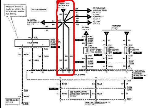
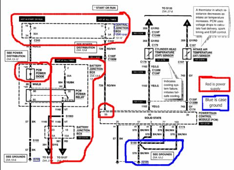
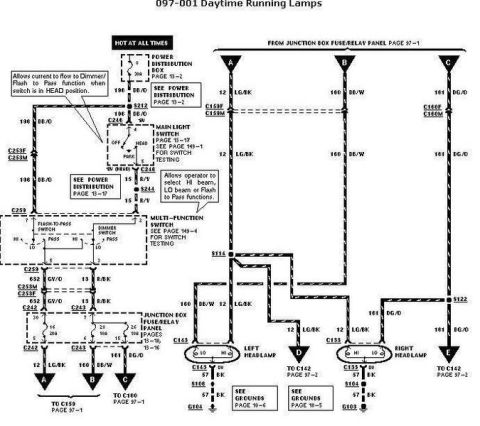
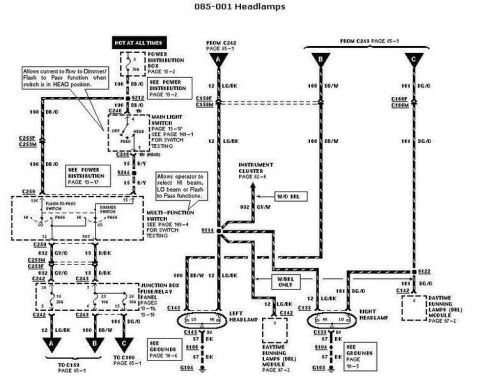
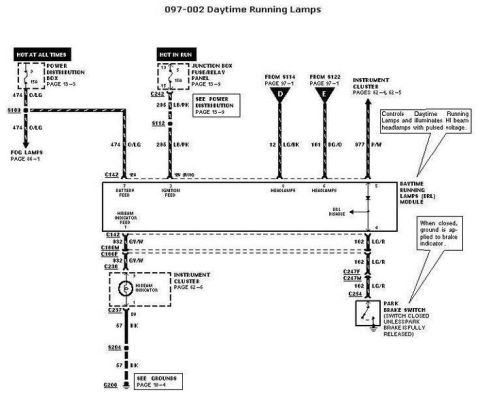









Wiring diagram routing battery junction box, MAF sensor, fuel pump relay and injector circuits into the powertrain control module.
Part of 2005-2014 Ford Mustang Wiring Diagrams
This is a Ford electrical wiring diagram page showing power feeds and grounds for the Powertrain Control Module (PCM), with the battery-supplied hot feeds highlighted in red by the uploader. Power originates from the Battery Junction Box (fuse J, referenced to DIA. 27-1) on circuit 361 RD, which splices at S127 and distributes to the fuel pump high/low relay, fuel pump relay, inertia switch relay, C120, and to PCM 12V power pins 71 and 97. The diagram also shows the Mass Air Flow (MAF) sensor circuit (with a note explaining it measures intake air for PCM fuel delivery calculations) using circuits 570 BK/WH, 967 LB/RD, and 968 TN/LB to PCM pins 88 and 36; the Turbine Shaft Speed (TSS) sensor on circuits 971 PK/BK and 970 DG/WH to pin 59; and fuel injectors #7 and #8 fed by 361 RD and controlled via 561 TN/RD (pin 72) and 562 LB (pin 98). PCM pins 16, 15, and 13 connect to the Data Link Connector (DLC) via circuits 914 TN/OG, 915 PK/LB, and 107 VT. Grounds route through S100 on 570 BK/WH to G100, with references to grounds diagram DIA. 10-2 and multiplex network DIA. 14-2.
Is this accurate? Sign in to help verify it.
Frequently asked questions
- Which PCM pins receive 12V battery power from the battery junction box?
- PCM pins 71 and 97 receive 12V power on circuit 361 (RD wire) from fuse J in the battery junction box, via splice S127.
- What wire colors and circuits are used for the Mass Air Flow (MAF) sensor?
- The MAF sensor uses circuit 570 BK/WH (0V ground), 967 LB/RD to PCM pin 88, and 968 TN/LB to PCM pin 36 through connector C141, with a 12V feed on 361 RD.
- What does the MAF sensor do according to this diagram?
- The callout states it measures the amount of intake air and is used by the PCM to help calculate fuel delivery.
- How are fuel injectors #7 and #8 wired to the PCM?
- Both injectors get 12V on circuit 361 RD (from S131). Injector #7 is controlled via 561 TN/RD to PCM pin 72 through C131; injector #8 via 562 LB to PCM pin 98 through C132 and connectors C120F/C120M and C174.
- Which circuits connect the PCM to the Data Link Connector (DLC)?
- PCM pin 16 uses 914 TN/OG to DLC pin 2, pin 15 uses 915 PK/LB (multiplex communication network, DIA. 14-2), and pin 13 uses 107 VT through C158M/C158F and C228F to DLC pin 13.






No comments yet.