Home/
Registry/
Ford/
Mustang/
1979-1993/
1990 Ford Mustang/
Photo
supermotors.net/registry/media/816161
Small Block Ford Engine Block Front Bolt Pattern Blueprint - Motor Plate Dimensions

Reference · 1979-1993 MustangAll 10 blueprints
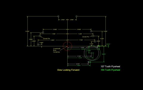
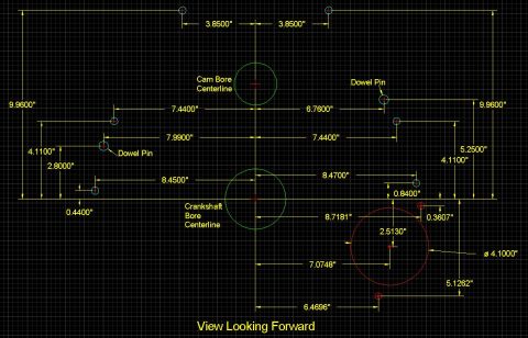
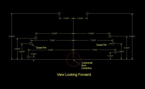
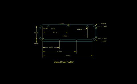
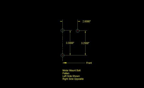
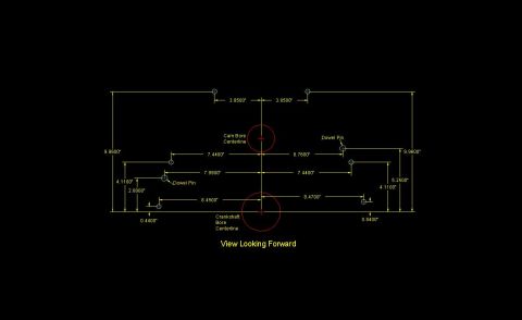
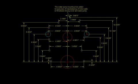
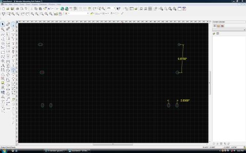
Dimensioned CAD blueprint of an engine motor plate showing bolt-hole and water-pump mounting locations with measurements.
Part of 1979-1993 Ford Mustang Blueprints
This document is a CAD-style blueprint drawing (black background with yellow dimension lines) showing the front bolt hole pattern of an engine block, uploaded as 'True Block Front.JPG'. It plots the locations of mounting/bolt holes relative to a vertical centerline and a horizontal baseline, with all dimensions given in inches to four decimal places. Horizontal offsets from the centerline include 0.6075", 2.1800", 2.9600", 4.5200", 4.6800" (multiple holes), 4.4400", 4.0651", 4.3800", 3.4500", and 4.0000" (both sides). Vertical heights above the baseline include 0.2400", 2.8400", 5.5400", 6.0200", 6.8000", 8.4000", 9.6400", 10.1800", and 10.8976". Two large red circles mark major features on the centerline (likely the camshaft and crankshaft bores), and two cyan circles mark larger holes at the 8.4000" height. A callout notes that one water pump mounting hole (at 0.6075" offset, 10.8976" height) was 'added for purposes of manufacturing of motor plate to fit between timing cover and water pump.' The drawing is useful for anyone fabricating a front motor plate, as it provides precise hole coordinates for the block face. No year, make, model, or engine designation appears on the drawing itself, though companion files in the album reference Small Block Ford.
Is this accurate? Sign in to help verify it.
Frequently asked questions
- What is the purpose of the extra water pump mounting hole shown in this drawing?
- Per the callout, the water pump mounting hole was added 'for purposes of manufacturing of motor plate to fit between timing cover and water pump.'
- How far apart are the two lowest bolt holes on the block front pattern?
- They are dimensioned at 4.0000" on each side of the centerline (8.0000" apart) and sit 0.2400" above the baseline.
- What is the height of the added water pump mounting hole?
- It is shown 10.8976" above the baseline and offset 0.6075" from the vertical centerline.
- Where are the two large (cyan) holes located?
- They are 8.4000" above the baseline, at 4.6800" to the left and 4.6800" to the right of the vertical centerline.
- What units are the dimensions in?
- All dimensions are given in inches (marked with " symbols), to four decimal places.

No comments yet.