Home/
Registry/
Ford/
Mustang/
1979-1993/
1990 Ford Mustang/
Photo
supermotors.net/registry/media/844093
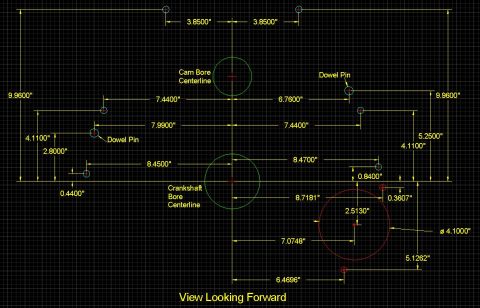
Ford Mustang K-Member Mounting Bolt Pattern Diagram - Bolt Spacing Dimensions
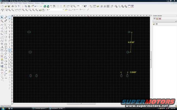
AutoSketch CAD screenshot of a crossmember mounting bolt-pattern drawing with partial dimensions shown.
This document is a screenshot of the AutoSketch CAD program displaying a drawing titled "K Member Mounting Bolt Pattern," uploaded to the gallery of a 1990 Ford Mustang. The drawing depicts a layout of bolt holes (drawn as slotted/oval markers with crosshair centers) representing the mounting bolt pattern for a K-member (front crossmember). Two dimensions are annotated in the drawing: a vertical spacing of 6.8750 inches between a pair of holes on the right side, and a horizontal spacing of 2.0300 inches between a pair of holes at the lower right. Additional undimensioned hole locations appear at the upper left, middle left, and lower left of the layout, positioned on the CAD grid with an inch-graduated ruler running across the top (13" through 59"). The status bar shows cursor coordinates and the taskbar shows a related open document titled "k member spacers." A reader can learn the two explicitly stated bolt-hole spacings (6.8750" and 2.0300") for the K-member mounting pattern; other hole positions would need to be scaled from the on-screen ruler. The document contains no year, model, engine, or part number text itself.
Is this accurate? Sign in to help verify it.
Frequently asked questions
- What bolt spacing dimensions are shown on the K-member mounting bolt pattern?
- Two dimensions are annotated: 6.8750" between the vertically paired holes on the right side, and 2.0300" between the horizontally paired holes at the lower right.
- What software was used to create this K-member bolt pattern drawing?
- The drawing is shown open in AutoSketch, with the document titled "K Member Mounting Bolt Pattern."
- How many bolt hole locations are shown in the drawing?
- Seven slotted hole markers are visible: one upper left, one middle left, two at lower left, a vertical pair at right, and a horizontal pair at lower right.
- Are all hole locations dimensioned in this drawing?
- No. Only two dimensions are labeled (6.8750" and 2.0300"); the remaining hole positions are shown on the grid without explicit dimensions.
Comments
More from this build



No comments yet.