Ford Bronco F-150-350 E-150-350 Parking Brake Cable Tension Limiter Adjustment

Reference · 1987-1991 BroncoAll 95 service procedures

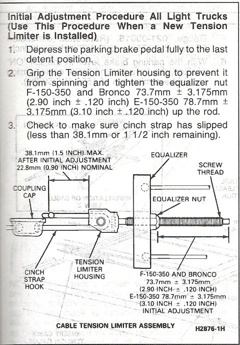













Step-by-step initial adjustment procedure for the parking-brake cable tension limiter assembly on light trucks and Bronco.
Part of 1987-1991 Ford Bronco Service Procedures
This scanned service manual page describes the initial adjustment procedure for the parking brake cable tension limiter on Ford light trucks (F-150 through F-350, Bronco, and E-150 through E-350), to be used when a new tension limiter is installed. The three-step procedure instructs the technician to: (1) depress the parking brake pedal fully to the last detent position; (2) grip the tension limiter housing to prevent it from spinning and tighten the equalizer nut up the rod, 73.7mm ± 3.175mm (2.90 inch ±.120 inch) for F-150-350 and Bronco, or 78.7mm ± 3.175mm (3.10 inch ±.120 inch) for E-150-350; and (3) verify the cinch strap has slipped, leaving less than 38.1mm (1-1/2 inch) remaining. A labeled illustration of the cable tension limiter assembly identifies the coupling cap, cinch strap hook, tension limiter housing, equalizer, equalizer nut, and screw thread, and shows the 38.1mm (1.5 inch) maximum / 22.8mm (0.90 inch) nominal dimension after initial adjustment along with the model-specific initial adjustment lengths. The figure carries reference number H2876-1H. Readers can learn exact adjustment specifications and the correct sequence for setting parking brake cable tension after tension limiter replacement.
Is this accurate? Sign in to help verify it.
Frequently asked questions
- What is the equalizer nut adjustment spec for the F-150-350 and Bronco parking brake tension limiter?
- Tighten the equalizer nut 73.7mm ± 3.175mm (2.90 inch ± .120 inch) up the rod.
- What is the parking brake tension limiter adjustment for E-150-350 vans?
- 78.7mm ± 3.175mm (3.10 inch ± .120 inch) up the rod.
- How do I know the cinch strap has slipped properly after adjustment?
- Check that less than 38.1mm (1-1/2 inch) is remaining; the nominal dimension after initial adjustment is 22.8mm (0.90 inch).
- What is the first step of the initial tension limiter adjustment procedure?
- Depress the parking brake pedal fully to the last detent position.
- When should this initial adjustment procedure be used?
- Use this procedure when a new tension limiter is installed, on all light trucks.






No comments yet.