SuperMotors SuperMotors SUPERMOTORS Search: try “orange Bronco on 35s”
Home/ Registry/ Ford/ Bronco/ 1992-1996/ “Eddie Bauer”/ Photo supermotors.net/registry/media/833676

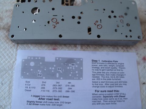
E4OD valve body calibration plate beside TransGo hole size chart…

E4OD valve body calibration plate beside TransGo hole size chart for 2nd, 3rd and 4th shift firmness
E4OD valve body calibration plate beside TransGo hole size chart for 2nd, 3rd and 4th shift firmnessOriginal file
E4OD valve body calibration plate beside TransGo hole size chart for 2nd, 3rd and 4th shift firmness

Reference · 1992-1996 BroncoAll 142 service procedures
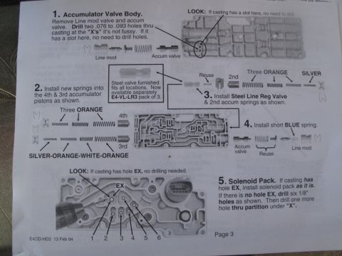
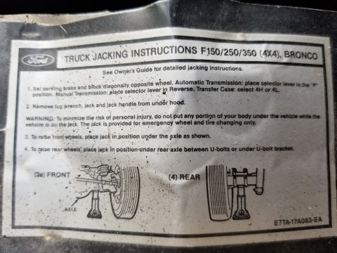
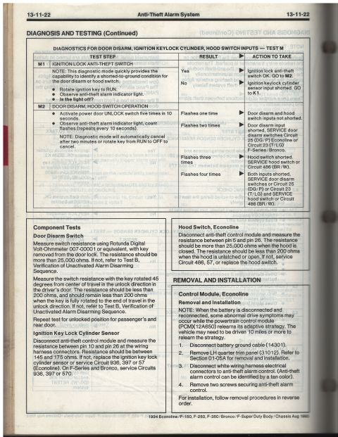
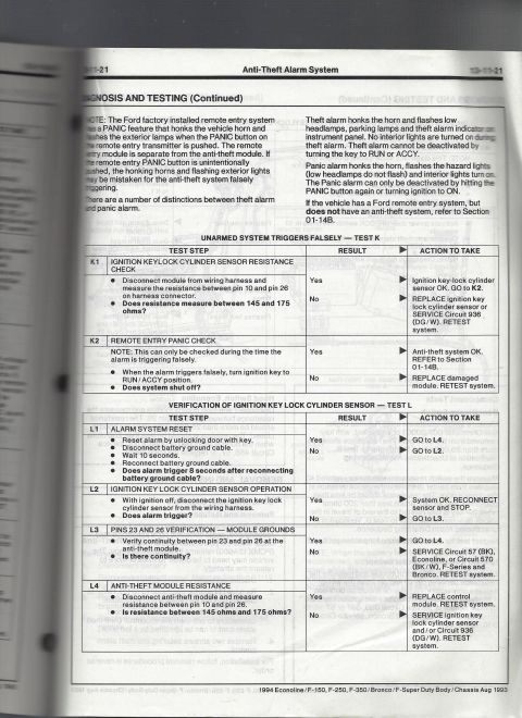
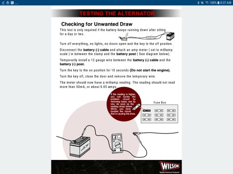
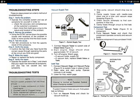
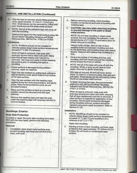
E4OD valve body calibration plate beside TransGo hole size chart for 2nd, 3rd and 4th shift firmness E4OD-HD2 valve body upgrade instructions with accumulator springs, drilling points and solenoid pack Ford E4OD Shift Kit Instructions Page 3 - Accumulator Springs & Solenoid Pack Ford E4OD Valve Body ID & Checkball Locations - Shift Kit Instructions Page 2 Ford EEC-IV Output State Check & Cylinder Balance Test - Code Reader Procedure Ford F150/F250/F350 4x4 & Bronco Truck Jacking Instructions Label E7TA-17A083-EA 1994 Ford Bronco/F-150/Econoline Anti-Theft Alarm Diagnosis Test M (13-11-22) 1994 Ford Bronco/F-150 Anti-Theft Alarm Diagnosis - Tests K & L (13-11-21) Parasitic Battery Draw Test Procedure - Checking for Unwanted Draw (Wilson) Ford Vacuum System Troubleshooting Steps & Tests - Supply, Leak, Component (EVTM) 1996 Ford Bronco Vacuum System Troubleshooting - Supply, Leak & Component Tests 1996 Ford Bronco/F-150 Exterior Trim & Body Side Moulding Removal - Pg 01-08-8 142service procedures1992-1996 Ford Bronco More reference TransGo E40D-HD2-D reprogramming kit instruction cover with Ford truck and Lincoln Navigator imagesBrochure 1996 Ford Bronco C202F 76-Pin Connector Pinout - EVTM Page 150-4Wiring diagram 1996 Ford Bronco/F-150 Distributor Exploded Parts Diagram & Installation 03-07A-6Exploded parts 1994 Ford Bronco Door Data Spec Plate - VIN, GVWR, Axle & Paint CodesSpec plate BMW M3 Owner's Manual Page 3 - Engine Compartment Component LocationsManual page 1993 Ford V8 Serpentine Belt Routing Diagram - Pulley Layout (Q2601-E)Schematic Brake Booster to Master Cylinder Adapter Plate Blueprint - Ford Bronco SwapBlueprint 1995 Ford Bronco 5.8L Emissions/VECI Label - Vacuum Hose Routing DiagramVacuum routing Ford Bronco/F-Series Fuse 18 (10A) - Speedometer, Air Bag, Shift ControlFuse chart Rod Bolt Stretch Monitoring Chart - 8-Rod V8 Connecting Rod Bolt Record SheetTorque spec

Calibration plate with 2nd, 3rd and 4th holes marked, beside TransGo Step 1 hole sizes for 6 Cyl, V8 & V10 and Diesel. A bigger hole makes a firmer shift.

Part of 1992-1996 Ford Bronco Service Procedures

AI caption · Photo 82 of 108

Size 2nd 3rd 4th 6 Cyl .076 .063-.067 .076-.086 V8 & V10 .094 073-082 .094 Diesel .110~116 .073-.082 .086-.096 A bigger hole makes the shift firmer. After road test: Slightly firmer shift make hole .010 larger. A la! firmer make hole .030 larger. Step 1. Calibration Plate Shift firmness is affected by engine power, axle ratio, weight, computer strategy, and clutch quality. There's no way to get it perfect on first try. This plate lets you choose an aver- age firmness, then make changes if needed. The 2nd, 3rd 51 4th holes are .053 in the plate furnished. Select a start firmness and drill holes to that size. After road test you may change sizes to adjust firmness. For sure read thls: When using a custom LOW STALL converter, especlally wlth Diesel make hole sizes same as 6 cyl, then road test. Then enlarge holes for any shift you want firmer.

Is this accurate? Sign in to help verify it.

Comments

No comments yet.

More 1992-1996 Broncos