Home/
Registry/
Ford/
Bronco/
1992-1996/
1996 Ford Bronco/
Photo
supermotors.net/registry/media/846911
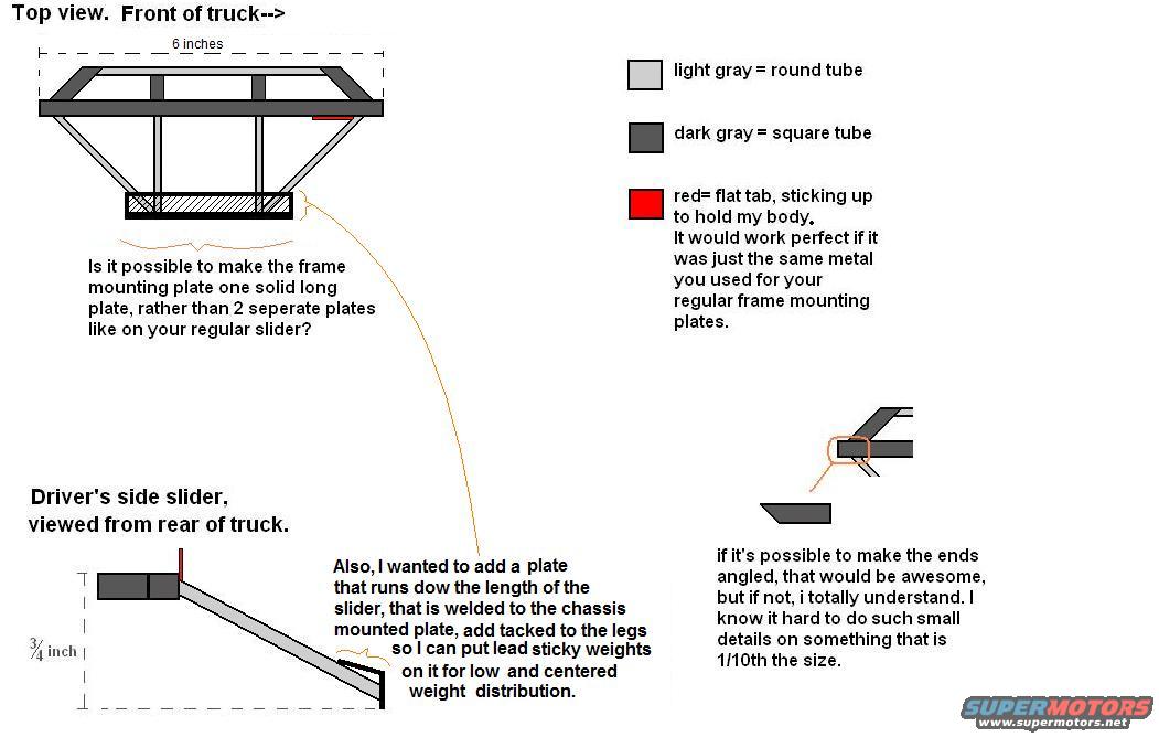
Custom Rock Slider Fabrication Sketch - Top & Side Views, Tube Legend (1/10 Scale)
Reference · 1992-1996 BroncoAll 95 schematics









User fabrication schematic of a frame mounting plate and rock slider with dimensions and round/square tube color key.
Part of 1992-1996 Ford Bronco Schematics
This document is a hand-annotated custom fabrication sketch (schematic) for a set of rock sliders, apparently intended as a build request to a fabricator for a 1/10th-scale model. It shows two views: a top view labeled with the front of the truck and a 6-inch overall length, and a driver's side slider viewed from the rear of the truck with a 3/4 inch height dimension. A color legend defines the materials: light gray shapes represent round tube, dark gray shapes represent square tube, and red represents a flat tab sticking up to hold the body, which the author asks to be made from the same metal as the regular frame mounting plates. The annotations include three requests to the builder: (1) whether the frame mounting plate can be made as one solid long plate instead of two separate plates as on the standard slider design; (2) adding a plate running the length of the slider, welded to the chassis-mounted plate and tacked to the legs, so lead sticky weights can be placed on it for low and centered weight distribution; and (3) whether the tube ends can be angled, acknowledging the difficulty of small details at 1/10th scale.
Is this accurate? Sign in to help verify it.
Frequently asked questions
- What do the colors in the slider diagram represent?
- Light gray = round tube, dark gray = square tube, and red = a flat tab sticking up to hold the body, ideally made from the same metal as the regular frame mounting plates.
- What are the dimensions shown on the slider sketch?
- The top view shows a 6-inch length, and the driver's side view (from the rear of the truck) shows a 3/4 inch dimension. The note states the piece is 1/10th the size of the full item.
- What modification is requested for the frame mounting plate?
- The author asks if the frame mounting plate can be made as one solid long plate rather than two separate plates like on the regular slider.
- Why does the author want an extra plate along the slider?
- A plate running the length of the slider, welded to the chassis-mounted plate and tacked to the legs, would let them attach lead sticky weights for low and centered weight distribution.
- What is requested for the slider tube ends?
- The author asks if the ends can be angled, but says they understand if not, since it's hard to do small details on something 1/10th the size.






No comments yet.