Home/
Registry/
Ford/
Bronco/
1992-1996/
1996 Ford Bronco/
Photo
supermotors.net/registry/media/893431
Upper Intake Manifold Exploded Parts Diagram - Callouts 1-10 (G97B03612)

Reference · 1992-1996 BroncoAll 169 exploded parts diagrams






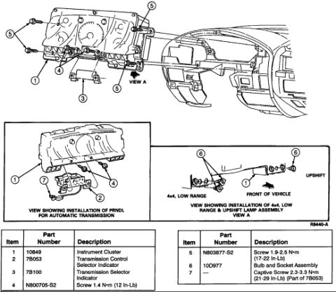
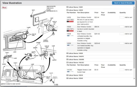
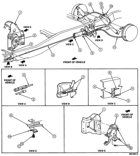
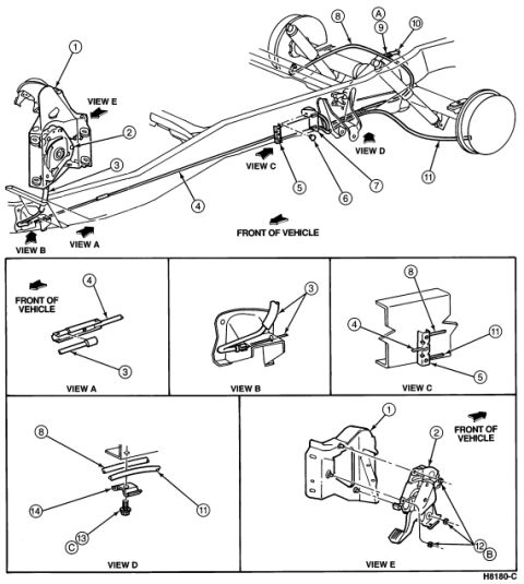
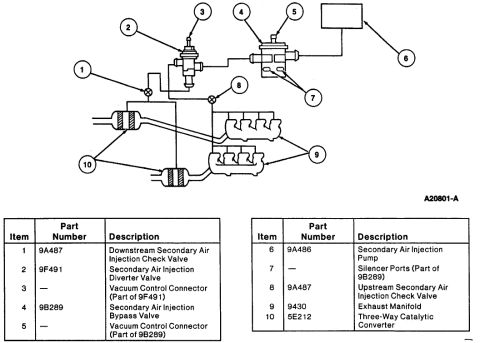
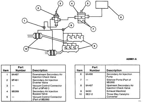
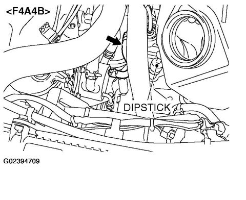
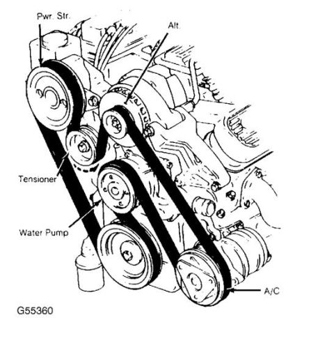






Exploded parts view of an intake manifold with numbered component callouts and fasteners.
Part of 1992-1996 Ford Bronco Exploded Parts Diagrams
This document is a single exploded-view parts illustration showing an upper intake manifold assembly with ten numbered callouts (1-10) and the figure reference code G97B03612. The drawing depicts the ribbed upper intake manifold body from a three-quarter perspective. Callouts identify the main manifold casting, individual runner/rib areas, top bosses or ports, two long mounting studs or bolts shown removed above the manifold, a bracket with studs at one end, a small fastener, and a cylindrical valve or solenoid component (with hose fitting) mounted at the opposite end of the manifold. No text legend accompanies the callout numbers, so the specific part names, part numbers, and torque specifications are not provided on this page, a companion legend page would be needed to decode the numbers. No year, make, model, or engine designation is printed on the illustration itself; the uploader's filename identifies it as an 'Impala upper intake,' although it was filed in a 1996 Ford Bronco gallery. A reader can use this diagram to understand the relative positions and fastener locations of the upper intake manifold components during disassembly or reassembly, provided they have the matching legend or service procedure.
Is this accurate? Sign in to help verify it.
Frequently asked questions
- What does this diagram show?
- An exploded parts illustration of an upper intake manifold assembly with ten numbered callouts (1-10) identifying the manifold body, fasteners, a bracket, and a cylindrical valve/solenoid component.
- Does the diagram include a legend naming each numbered part?
- No. Only the callout numbers 1 through 10 appear; no component names, part numbers, or torque values are printed on this page.
- What figure reference code appears on the drawing?
- G97B03612, printed at the lower left of the illustration.
- Are any fasteners shown separately in the exploded view?
- Yes. Two long studs/bolts are shown removed above the manifold (callout 7) and a small bolt/screw is shown at the upper left (callout 9).
- Does the document state which vehicle or engine it applies to?
- No. The illustration contains no year, make, model, or engine information.






No comments yet.