1989 Ford Bronco Start/Ignition Wiring Diagram 5.0L 5.8L 7.5L - TFI & Coil
Reference · 1987-1991 BroncoAll 175 wiring diagrams
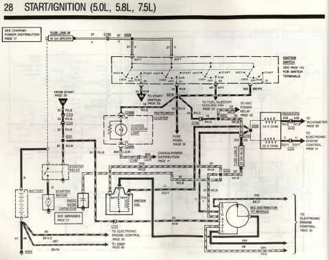
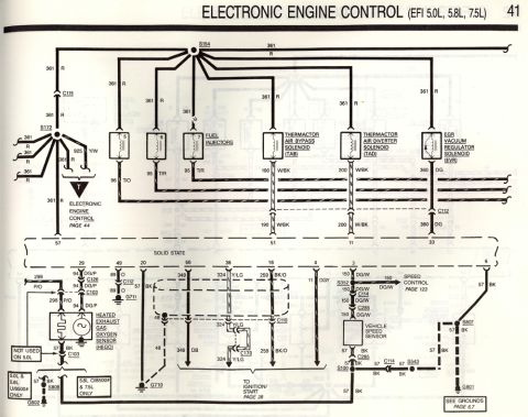
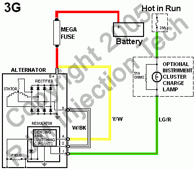









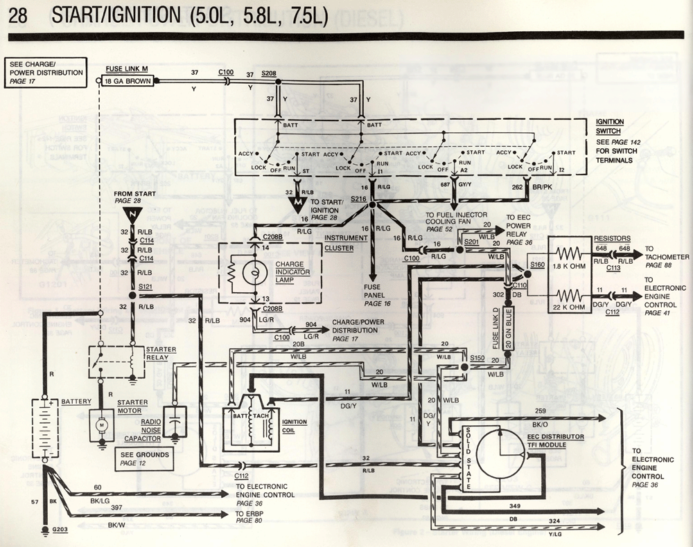
Wiring diagram of the start/ignition system showing ignition switch terminals, starter relay, TFI module, and charge circuits.
Part of 1987-1991 Ford Bronco Wiring Diagrams
This is page 28 of a Ford factory-style wiring diagram set covering the START/IGNITION system for 5.0L, 5.8L, and 7.5L gasoline engines. The diagram traces power from Fuse Link M (18 GA brown) through connector C100 and splice S208 to the ignition switch BATT terminals, showing switch positions (LOCK, OFF, RUN, ACCY, START) and terminal outputs: circuit 32 R/LB to the starter (ST), 16 R/LG (I1), 687 GY/Y (A2), and 262 BR/PK (I2). It shows the starter relay, battery, starter motor, and radio noise capacitor circuits, plus grounds G203 and circuits 57 BK, 60 BK/LG, and 397 BK/W. The instrument cluster charge indicator lamp circuit (16 R/LG in, 904 LG/R out via C208B and C100) is detailed. Ignition coil BATT/TACH wiring (20 W/LB, 11 DG/Y), the EEC distributor TFI module with outputs 259 BK/O, 349 DB, and 324 Y/LG to the EEC, resistor network (1.8K and 22K ohm) feeding the tachometer (648 R/LB) and EEC (11 DG/Y), and Fuse Link D (20 GA green-blue) are all shown. Cross-references point to related pages: charge/power distribution (17), fuse panel (16), grounds (12), fuel injector cooling fan (52), EEC (36, 41), tachometer (88), ERBP (80), and switch terminals (142).
Applies to: Ford F-Series/Bronco 5.0L/5.8L/7.5L, start/ignition wiring page 28 (year not printed) (factory). Matches this vehicle.
Reviewed by the SuperMotors Editorial Team · Spotted an error? Suggest a correction
Is this accurate? Sign in to help verify it.
Frequently asked questions
- What engines does this start/ignition wiring diagram cover?
- The page header states it covers the 5.0L, 5.8L, and 7.5L engines.
- What wire feeds the starter relay from the ignition switch?
- Circuit 32 R/LB (red/light blue) runs from the ignition switch ST terminal through connectors C114 and splice S121 to the starter relay.
- What size and color is Fuse Link M?
- Fuse Link M is 18 gauge brown, feeding circuit 37 (yellow) to the ignition switch BATT terminals via C100 and S208.
- What are the wire colors at the EEC distributor TFI module?
- The TFI module connects to the EEC via 259 BK/O, 349 DB, and 324 Y/LG, with 20 W/LB, 11 DG/Y, and 32 R/LB feeds shown.
- What resistor values are used in the tachometer/EEC ignition circuit?
- A 1.8 K ohm and a 22 K ohm resistor are shown, with 648 R/LB going to the tachometer (page 88) and 11 DG/Y to the electronic engine control (page 41).






No comments yet.