1995 Ford Bronco E4OD Transmission Wiring Diagram (EVTM Page 30-1)
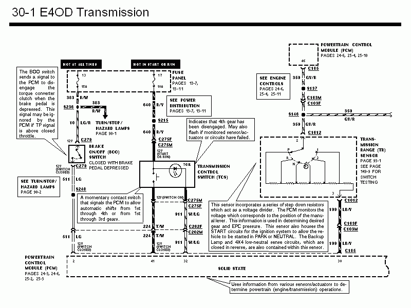
Wiring diagram for the E4OD transmission showing brake on/off switch, transmission control switch, and range sensor circuits.
Part of 1987-1991 Ford Bronco Wiring Diagrams
This is page 30-1 of the 1995 Ford Bronco Electrical and Vacuum Troubleshooting Manual (EVTM), covering the E4OD automatic transmission wiring. The diagram shows power feeds from the fuse panel, fuse 13 (15A, hot at all times) and fuse 17 (10A, hot in start or run), routing to the Brake On/Off (BOO) switch, the Transmission Control Switch (TCS) with its Transmission Control Indicator Lamp (TCIL), the Transmission Range (TR) sensor, and the Powertrain Control Module (PCM). Wire circuits and colors are labeled, including 383 R/W, 10 LG/R, 511 LG, 640 R/Y, 911 W/LG, 224 T/W, 359 GY/R, and 199 LB/Y, along with connectors C279, C275F/M, C202F/M, C185, C103M/F, C1012, C165 and splices S236, S240, S215, S137, S146. Explanatory callouts describe how the BOO switch signals the PCM to disengage the torque converter clutch, how the TCS enables/disables overdrive (flashing indicates 4th gear disengaged or a fault), and how the TR sensor acts as a voltage divider that reports manual lever position, houses the START circuit, and contains backup lamp and 4x4 low-neutral sense circuits. Cross-references point to related pages for power distribution, engine controls, backup lamps, and TR sensor testing.
Is this accurate? Sign in to help verify it.
Frequently asked questions
- What does the Brake On/Off (BOO) switch do in the E4OD system?
- The BOO switch sends a signal to the PCM to disengage the torque converter clutch when the brake pedal is depressed. The PCM may ignore this signal if the TP signal is above closed throttle.
- What does it mean when the transmission control indicator lamp (TCIL) flashes?
- It indicates that 4th gear has been disengaged, and it may also flash if monitored sensors/actuators or circuits have failed.
- What fuses power the E4OD transmission circuits on this diagram?
- Fuse 13 (15A, hot at all times) and fuse 17 (10A, hot in start or run) in the fuse panel, referenced to pages 13-7 and 13-11.
- What does the Transmission Range (TR) sensor do?
- It uses a series of step-down resistors as a voltage divider; the PCM monitors the voltage corresponding to manual lever position to determine desired gear and EPC pressure. It also houses the START circuits (allowing starting in PARK or NEUTRAL) and contains the backup lamp and 4x4 low-neutral sense circuits, which close in reverse.
- Where is TR sensor switch testing covered?
- The diagram directs readers to page 149-9 for switch testing and page 93-1 for the TR sensor/backup lamps.
Comments
More from this build














No comments yet.