1989 Ford Bronco EEC Wiring Diagram Pg 42 - EFI 5.0L 5.8L 7.5L Injectors & Sensors
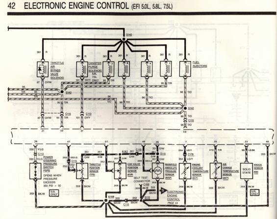
Wiring diagram of sensor circuits including TPS, MAP, ECT, ACT, knock and power-steering pressure sensors with color codes.
Part of 1987-1991 Ford Bronco Wiring Diagrams
This is page 42 of a Ford wiring diagram set covering the Electronic Engine Control (EEC) system for EFI 5.0L, 5.8L, and 7.5L engines. The upper portion of the schematic shows power distribution from splice S140 on circuit 361 (Red) to the Throttle Air Bypass Valve Solenoid, the Canister Purge Solenoid (5.8L/7.5L applications), and the fuel injectors. Injector control circuits 95 (T/R) and 96 (T/O) route through splices S143 and S142 and connectors C113 and C115 to EEC processor pins 21, 59, 31, and 58. The lower portion details the sensor circuits into processor pins 24, 47, 27, 45, 26, 7, 25, 23, and 46: the Power Steering Pressure Switch (PSPS, 5.0L only, opens above 350 PSI ± 50), Throttle Position Sensor (TPS), EGR Valve Position Sensor (EVP), Manifold Absolute Pressure Sensor (MAP), Engine Coolant Temperature Sensor (ECT), Air Charge Temperature Sensor (ACT), and Knock Sensor (KS, 5.0L only). Sensor grounds converge on circuit 359 (BK/W) through splices S168 and S115 and the Self Test Connector (C168). A note directs the reader to the continuation of the EEC diagram on page 44. All wire circuit numbers and color codes are labeled throughout.
Is this accurate? Sign in to help verify it.
Frequently asked questions
- What circuit powers the fuel injectors on the 5.0L/5.8L/7.5L EFI system?
- Circuit 361, a Red wire, feeds all fuel injectors, the Throttle Air Bypass Valve Solenoid, and the Canister Purge Solenoid from splice S140.
- What wire colors are the injector control circuits?
- Circuit 95 is Tan/Red (T/R) and circuit 96 is Tan/Orange (T/O); they route through splices S143 and S142 to EEC processor pins 21, 59, 31, and 58.
- When does the Power Steering Pressure Switch (PSPS) open?
- The diagram notes it opens when pressure exceeds 350 PSI ± 50, and it is used on the 5.0L only. It connects to processor pin 24 via circuit 330 Y/LG.
- Which sensors are 5.0L only on this diagram?
- The Power Steering Pressure Switch (PSPS) and the Knock Sensor (KS) are both marked '5.0L ONLY'.
- What wire is the common sensor ground/return?
- Circuit 359, Black/White (BK/W), is the return for the TPS, EVP, MAP, ECT, ACT, KS, PSPS, and the Self Test Connector, joining at splices S168 and S115.
Comments
More from this build














No comments yet.