SuperMotors SuperMotors SUPERMOTORS Search: try “orange Bronco on 35s”
Home/ Registry/ Ford/ Bronco/ 1987-1991/ “Eddie Bauer”/ Photo supermotors.net/registry/media/853555

Ford Racing M-11000-A50/A75/B50/B75 starter wiring, Figure 2, wi…

Ford Racing M-11000-A50/A75/B50/B75 starter wiring, Figure 2, with hand-drawn solenoid terminal sketch
Ford Racing M-11000-A50/A75/B50/B75 starter wiring, Figure 2, with hand-drawn solenoid terminal sketchOriginal file
Ford Racing M-11000-A50/A75/B50/B75 starter wiring, Figure 2, with hand-drawn solenoid terminal sketch

Reference · 1987-1991 BroncoAll 95 service procedures

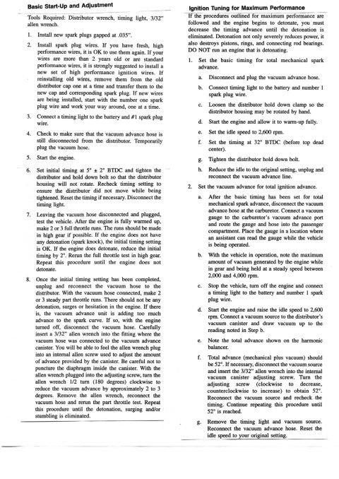
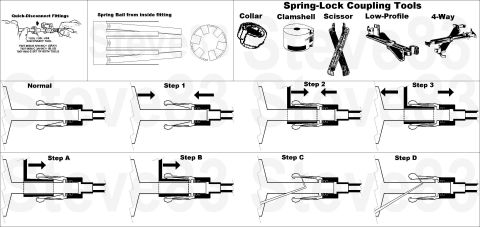
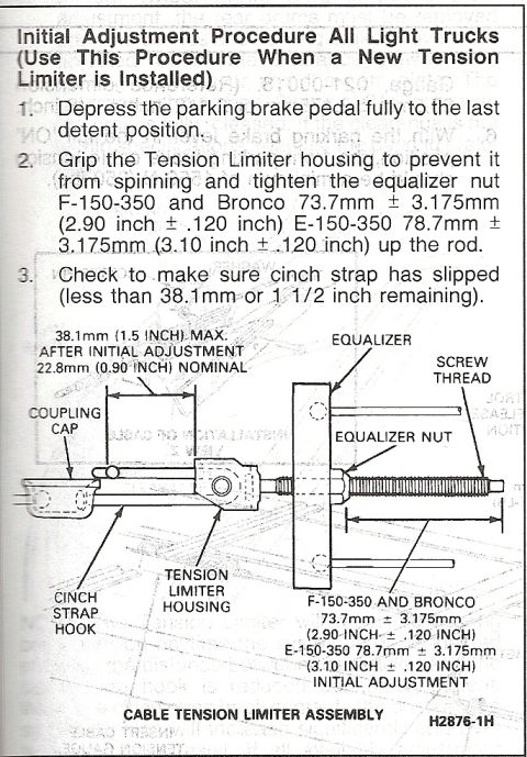
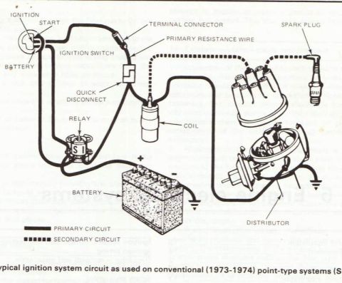
1995 Ford MLP/TR Sensor Connector Swap Instructions - I.S. 6628A Sheet 3 of 6 Ford I.S. 6628A sheet 2 of 6, 1995 MLP/TR sensor connector assembly swap steps 6 through 12 1995 Ford MLP/TR Sensor Connector Swap Instructions - E4OD Kit F5TZ-7A247-AVMR Ford Racing M-11000-A50/A75/B50/B75 starter wiring, Figure 2, with hand-drawn solenoid terminal sketch Vacuum Advance Distributor Tune-Up & Timing Adjustment Procedure - Ford Bronco Ford PIP/SPOUT Wiring Repair for DTC 211 Miss/Stall - F-150 4.9L Diagrams Ford Fuel Line Quick-Disconnect & Spring-Lock Coupling Tools Diagram (T90T-9550) Ford Bronco F-150-350 E-150-350 Parking Brake Cable Tension Limiter Adjustment 95service procedures1987-1991 Ford Bronco More reference 1973-1974 Ford Point-Type Ignition System Circuit Diagram - Coil & DistributorWiring diagram Ford Thermactor Air Bypass Valve Cutaway Diagram - Port IdentificationSchematic Ford 5.8L important engine information decal with 10° BTDC timing check and ASF-32C plugSpec plate Ford 5.0L V8 PCV Valve & Hose Routing Diagram - 9A474, 6B890, 6A664Exploded parts Ford 5.0L/5.8L Air Throttle Body Assembly Diagram - Canister Purge Ports & TPSManual page 1990 Bronco Major Standard Equipment sheet with interior features and functional specs by trimBrochure Borgeson Steering Intermediate Shaft Measurement Diagram - U-Joint Length B & CBlueprint Ford Thermactor Combination Valve Diagram - Air Bypass/Control Ports LabeledVacuum routing 1990 Ford Bronco Fuse Panel Diagram: Fuse Positions, Amps & Circuits (11-2)Fuse chart Ford V8 Intake Manifold Bolt Tightening Sequence Diagram - Stud LocationsTorque spec

Ford Racing starter instructions, steps 17-20: #12 gauge wire to the starter relay "A" post, plus a hand-drawn sketch of the owner's solenoid terminals.

Part of 1987-1991 Ford Bronco Service Procedures

AI caption · Photo 530 of 1787

M-110M-A50lA75/Bsn/575 Ford RacIng sumr INSTALLATION INSTRUCTIONS w my a: m Mm. w .2 mowmm m mama wwmunmum a mum: mm w str m mam: Wm(mmlm'A mummum (rm-m mum mmm O I 0 aljdow s 5 G Tm. "Hm LIII ' (588)46341 ass Q mm r... m. mm. n mm. m. nu... FmIlnuum. P110 a nu AMI0061

Is this accurate? Sign in to help verify it.

Comments

No comments yet.

More 1987-1991 Broncos