Ford Fuel Line Quick-Disconnect & Spring-Lock Coupling Tools Diagram (T90T-9550)
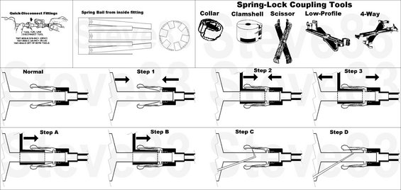
Service procedure showing spring-lock coupling tools and numbered steps for connecting and disconnecting fuel line fittings.
This document is a service reference diagram covering Ford fuel line quick-disconnect (spring-lock) fittings and the special tools used to separate them. The top-left panel illustrates a fuel line disconnect tool in use on a quick-disconnect fitting and lists the tool part numbers: T90T-9550-B for 5/16-inch fittings (gray), T90T-9550-C for 3/8-inch fittings (blue), and T90T-9550-S for the set of both tools. A second panel shows the spring bail (garter spring) as viewed from inside the fitting. The top-right panel, titled 'Spring-Lock Coupling Tools,' illustrates five styles of disconnect tools: Collar, Clamshell, Scissor, Low-Profile, and 4-Way. The lower two rows contain cross-section diagrams of the coupling. The first sequence shows the 'Normal' connected state followed by Steps 1-3, illustrating how the tool is inserted into the fitting and pushed to expand the spring so the male and female halves can be pulled apart. The second sequence, Steps A-D, shows an alternate disconnection method, ending with views of the separated fitting halves and the internal spring/clip. A reader can learn which Ford tool part numbers fit which line sizes and visually follow the disconnection procedure for these fuel filter/fuel line couplings.
Is this accurate? Sign in to help verify it.
Frequently asked questions
- What tool do I need to disconnect Ford fuel line quick-disconnect fittings?
- The document lists a fuel line disconnect tool: T90T-9550-B for 5/16-inch fittings (gray), T90T-9550-C for 3/8-inch fittings (blue), or T90T-9550-S, which is the set of both tools.
- What color is the 5/16-inch Ford fuel line disconnect tool?
- The 5/16-inch tool, part number T90T-9550-B, is gray; the 3/8-inch tool, T90T-9550-C, is blue.
- What types of spring-lock coupling tools are shown?
- Five styles are illustrated: Collar, Clamshell, Scissor, Low-Profile, and 4-Way.
- How does the disconnect procedure work on these fittings?
- The diagrams show the fitting in its normal connected state, then a step-by-step sequence (Steps 1-3 and Steps A-D) where the disconnect tool is pushed into the fitting to release the internal spring bail, allowing the two halves to be pulled apart.
- What holds the quick-disconnect fitting together?
- A spring bail (garter spring) inside the fitting, shown in the 'Spring Bail from inside fitting' illustration, retains the coupling until released by the tool.
Comments
More from this build













No comments yet.