Ford PIP/SPOUT Wiring Repair for DTC 211 Miss/Stall - F-150 4.9L Diagrams
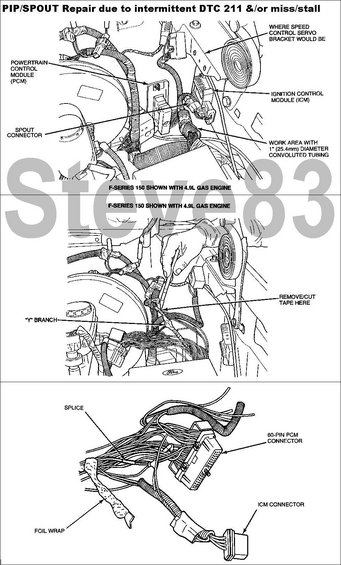
Service procedure for PIP/SPOUT DTC 211 repair showing photos of harness splicing, foil wrap and PCM/ICM connectors.
Part of 1987-1991 Ford Bronco Service Procedures
This document is a set of three service illustrations supporting a PIP/SPOUT wiring repair procedure for vehicles experiencing intermittent Diagnostic Trouble Code (DTC) 211 and/or an engine miss or stall condition. The illustrations, labeled as an F-Series 150 shown with the 4.9L gas engine, identify the key underhood components involved in the repair: the Powertrain Control Module (PCM), the Ignition Control Module (ICM), the SPOUT connector, the location where the speed control servo bracket would be mounted, and the work area covered with 1" (25.4 mm) diameter convoluted tubing. The second illustration shows a technician's hand locating the "Y" branch of the harness and indicates where to remove or cut the harness tape. The third illustration is a close-up of the harness showing the splice location, the 60-pin PCM connector, the ICM connector, and the foil wrap on the harness. A reader can learn where to access and open the ignition/PCM wiring harness to inspect or repair the PIP/SPOUT circuits associated with DTC 211 miss/stall complaints. The page contains callout labels only, with no written step-by-step text, part numbers, or wire color codes.
Is this accurate? Sign in to help verify it.
Frequently asked questions
- What problem does this PIP/SPOUT repair address?
- It addresses an intermittent DTC 211 and/or an engine miss or stall condition, repaired via the PIP/SPOUT wiring.
- What vehicle and engine are shown in the illustrations?
- The illustrations show an F-Series 150 with the 4.9L gas engine.
- Which components are identified in the diagrams?
- The Powertrain Control Module (PCM), Ignition Control Module (ICM), SPOUT connector, 60-pin PCM connector, ICM connector, harness splice, foil wrap, the "Y" branch, and the location where the speed control servo bracket would be.
- Where is the work area for this repair?
- The work area is in the harness section covered with 1" (25.4 mm) diameter convoluted tubing near the SPOUT connector and ICM, and tape is removed/cut at the "Y" branch of the harness.
- What harness features are shown at the PCM end of the harness?
- The close-up shows the splice location, foil wrap on the harness, the 60-pin PCM connector, and the ICM connector.
Comments
More from this build














No comments yet.