TFI-IV / DI Ignition Coil Secondary Resistance Test Diagram - Ford Bronco

Reference · 1987-1991 BroncoAll 95 service procedures
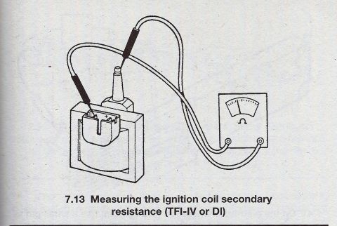








Service figure 7.13 illustrating how to measure ignition coil secondary resistance with an ohmmeter on a TFI-IV or DI system.
Part of 1987-1991 Ford Bronco Service Procedures
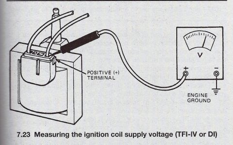
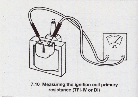
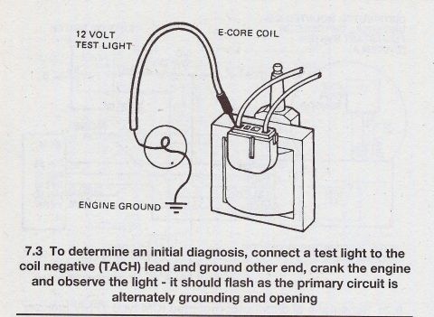
This document is a single illustrated figure from an automotive service manual, labeled '7.13 Measuring the ignition coil secondary resistance (TFI-IV or DI)'. The line drawing shows a Ford-style E-core (TFI) ignition coil with its high-tension tower and low-voltage connector, connected to an analog ohmmeter. One meter test lead is inserted into the coil's secondary high-tension tower, while the other test lead is touched to a terminal in the coil's primary connector. The meter face displays an ohm (Ω) symbol, indicating a resistance measurement. The figure demonstrates the correct probe placement for checking the secondary winding resistance on TFI-IV (Thick Film Ignition) or DI (Distributorless Ignition) coils. A reader can learn how to physically connect an ohmmeter to test the secondary circuit of this coil type; the figure itself does not state resistance specification values, which would be given in the accompanying manual text. This image is part of a series of coil-testing scans (initial diagnosis, primary resistance, supply voltage) uploaded to a 1990 Ford Bronco gallery on SuperMotors.net.
Is this accurate? Sign in to help verify it.
Frequently asked questions
- How do you measure secondary resistance on a TFI-IV ignition coil?
- Per figure 7.13, connect an ohmmeter with one test lead inserted into the coil's high-tension (secondary) tower and the other lead touching a terminal in the coil's low-voltage connector.
- What tool is used for this ignition coil test?
- An ohmmeter (the illustrated meter shows an Ω symbol) is used to measure resistance.
- Which ignition systems does this test apply to?
- The caption states it applies to TFI-IV or DI ignition systems.
- Does this document give the resistance specification values?
- No. The figure only shows the test hookup; no ohm specification values are printed in this scan.






No comments yet.