Ford TFI-IV / DI Ignition Coil Supply Voltage Test Diagram - Coil (+) Terminal
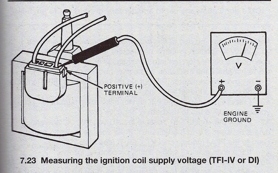
Service figure 7.23 showing how to measure ignition coil supply voltage at the positive terminal with a voltmeter on a TFI-IV or DI system.
This document is a single illustration (figure 7.23) from an automotive service manual showing how to measure the ignition coil supply voltage on a Ford TFI-IV or DI (distributor ignition) system. The line drawing depicts an E-core style ignition coil with its connector, and a test probe back-probing the coil's positive (+) terminal, which is called out with an arrow and the label 'POSITIVE (+) TERMINAL.' The probe lead runs to the positive (+) input of an analog voltmeter (marked with a 'V' scale and needle), while the meter's negative (−) terminal is connected to 'ENGINE GROUND,' indicated by a ground symbol. A reader learns the correct hookup for checking whether battery/ignition supply voltage is reaching the coil primary: probe the coil positive terminal with the voltmeter positive lead and ground the negative lead to the engine. The figure caption identifies the test as applicable to TFI-IV or DI ignition systems. No specific voltage specifications, year/model applicability, or part numbers appear in this scan; it is one page of a multi-part TFI coil testing sequence (companion scans cover initial diagnosis and primary/secondary resistance checks).
Is this accurate? Sign in to help verify it.
Frequently asked questions
- How do I test the ignition coil supply voltage on a Ford TFI-IV or DI ignition system?
- Per figure 7.23, connect a voltmeter's positive (+) lead to the coil's positive (+) terminal and the voltmeter's negative (−) lead to engine ground, then read the voltage.
- Which coil terminal do I probe when checking supply voltage?
- The diagram points to the POSITIVE (+) TERMINAL on the ignition coil connector as the point to probe with the voltmeter's positive lead.
- Where does the voltmeter's negative lead connect during this test?
- The negative (−) lead of the voltmeter is connected to ENGINE GROUND, as shown by the ground symbol in the diagram.
- What ignition systems does this test apply to?
- The caption states it applies to TFI-IV or DI (distributor ignition) systems.
Comments
More from this build














No comments yet.