1990 Ford Bronco 5.0L/5.8L Engine Component Location Diagram - EVTM 151-4

Reference · 1987-1991 BroncoAll 110 schematics
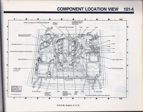
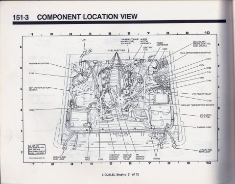
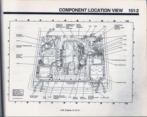
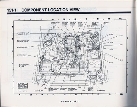


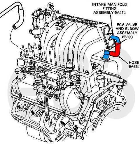
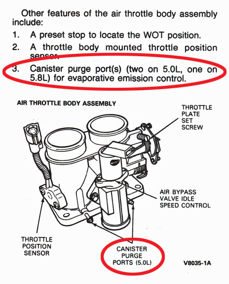


Ford EVTM component location view 151-4 for 5.0L/5.8L engines (2 of 2); maps MAP sensor, knock sensor, TAD/EGR control solenoids, fuel pump relay, ACT sensor, canister purge and connectors.
Part of 1987-1991 Ford Bronco Schematics
This document is page 151-4 of a Ford factory electrical/vacuum troubleshooting manual (EVTM), titled "Component Location View." It presents a detailed line-art illustration of the engine compartment for the 5.0L/5.8L engine (labeled "2 of 2"), overlaid on a lettered/numbered locator grid (columns 1-10, rows A-F). Callouts identify the physical locations of key underhood electrical components and connectors, including the manifold absolute pressure (MAP) sensor, knock sensor, thermactor air diverter (TAD) solenoid, EGR control solenoid, A/C clutch cycling pressure switch, blower motor, air charge temperature sensor, starter relay, fuel pump relay, oil pressure sender, engine coolant temperature sensor, canister purge solenoid, timing test lead, daytime running lamps (DRL) module, RH and LH headlamps, and fuse links A, F, G, L, M, N, P & W. Numbered harness connectors identified include C100, C105, C106, C110, C118, C129, C133, C151, C152, and C154, plus ground points G100 and G104. The page carries reference number FPS-12129-90 (4 of 12), indicating a 1990 publication, and a note stating the illustration and grid are not to be used for reporting vehicle repair locations. This page is useful for locating sensors, relays, connectors, and grounds on a 1990 Ford 5.0L/5.8L engine.
Is this accurate? Sign in to help verify it.
Frequently asked questions
- Where is the fuel pump relay on a 1990 Ford 5.0L/5.8L engine?
- The diagram shows the fuel pump relay on the passenger (left in view) side of the engine compartment, called out on the right side of the illustration above the oil pressure sender callout.
- What connectors are identified in this 5.0L/5.8L component location view?
- Connectors C100, C105, C106, C110, C118, C129, C133, C151, C152, and C154 are called out, along with ground points G100 and G104.
- Which fuse links are shown in the engine compartment on this diagram?
- Fuse links A, F, G, L, M, N, P, & W are called out near the driver's side of the engine compartment.
- What sensors are located in this component location view?
- The manifold absolute pressure sensor, knock sensor, air charge temperature sensor, engine coolant temperature sensor, and oil pressure sender, plus the EGR control solenoid, thermactor air diverter (TAD) solenoid, and canister purge solenoid.
- Does this page cover the whole engine compartment layout?
- It is captioned '5.0L/5.8L Engine (2 of 2)' and is sheet FPS-12129-90 (4 of 12), so it is one page of a multi-page component location set.






No comments yet.