Ford 5.8L Heater Hose Routing Diagram - AOD, 4R70W & E4OD (Bronco/F-Series)

Reference · 1987-1991 BroncoAll 112 schematics
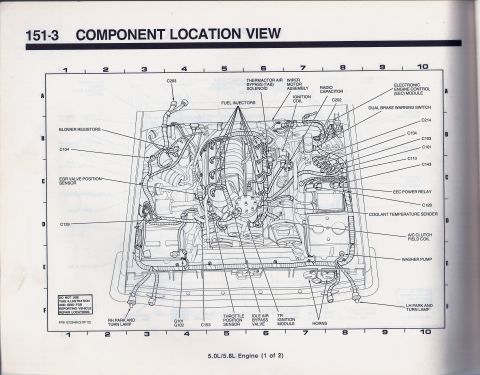
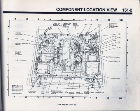
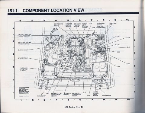
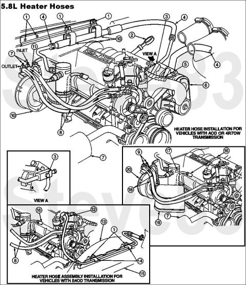











Heater hose routing schematic for the 5.8L engine showing numbered hose connections for AOD/4R70W and E4OD installations.
Part of 1987-1991 Ford Bronco Schematics
This document is a factory-style schematic illustration showing heater hose routing for the Ford 5.8L (351W) V8 engine. The page, titled "5.8L Heater Hoses," contains three main line drawings with numbered callouts (1 through 20). The large upper diagram depicts heater hose installation for vehicles equipped with the AOD or 4R70W automatic transmission, with the heater core INLET and OUTLET connections labeled on the left side of the engine and an arrow indicating "VIEW A." A small inset labeled "VIEW A" shows a close-up detail of a hose fitting/bracket (callout 3). A second large diagram at the bottom left shows the heater hose assembly installation for vehicles with the E4OD transmission, and a third diagram at the lower right shows additional hose routing around the accessory drive area with callouts 7, 9, 16, 17, 18, 19, and 20. No parts legend, part numbers, or torque specifications appear on this page, only numbered callouts referencing an external parts list. A reader can learn how the heater hoses route across the front of the 5.8L engine, how routing differs between AOD/4R70W and E4OD transmission applications, and where the heater core inlet and outlet connect.
Is this accurate? Sign in to help verify it.
Frequently asked questions
- Does heater hose routing on the 5.8L differ by transmission?
- Yes. The document shows two separate installations: one heater hose installation for vehicles with AOD or 4R70W transmission, and a different heater hose assembly installation for vehicles with the E4OD transmission.
- Where are the heater core inlet and outlet shown on the 5.8L diagram?
- The INLET and OUTLET connections are labeled on the left side of the main diagram, at the firewall/heater core end of the hoses near callouts 7 and 11.
- What is VIEW A in this diagram?
- VIEW A is a close-up inset showing detail of a hose connection/fitting identified by callout number 3, referenced by an arrow on the main AOD/4R70W diagram.
- Does this schematic include part numbers for the heater hoses?
- No. The diagrams use numbered callouts (1-20) only; no part numbers, legend, or torque values are printed on this page.






No comments yet.