1990 Ford Bronco 4.9L Engine Component Location View 151-2 - Connectors & Sensors

Reference · 1987-1991 BroncoAll 111 schematics
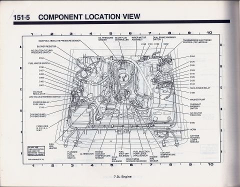
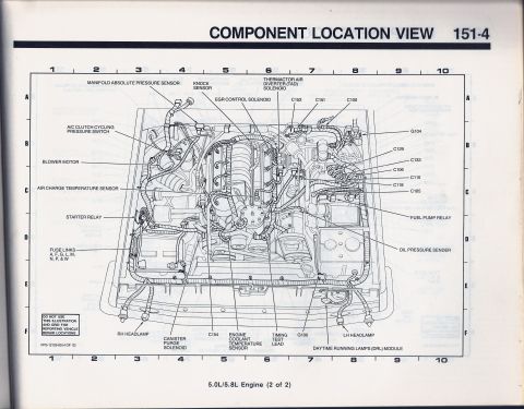
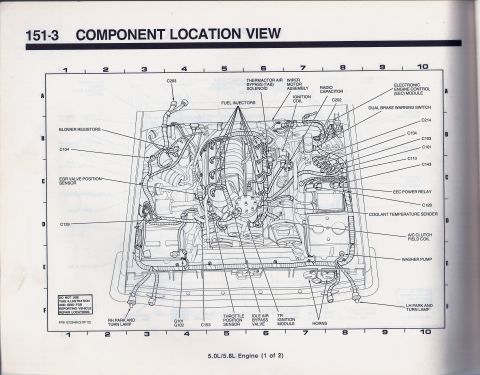
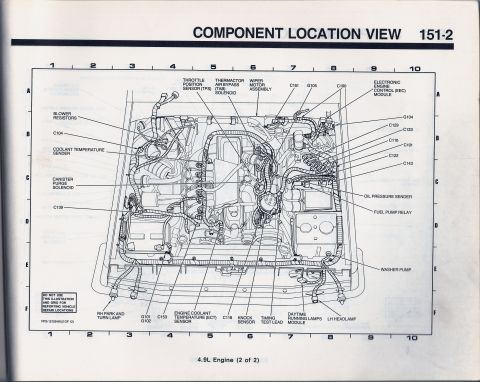
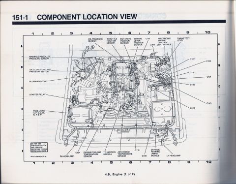














Component location view of the 4.9L engine showing TPS, EEC module, sensors, relays, and connector callouts across the engine compartment.
Part of 1987-1991 Ford Bronco Schematics
This document is page 151-2 of a Ford factory electrical/vacuum troubleshooting manual, titled "Component Location View," showing the second of two engine compartment illustrations for the 4.9L (300 cu in inline six) engine. The line drawing depicts a top-down view of the engine bay with an alphanumeric locator grid (columns 1-10, rows A-F). Callout leaders identify the physical locations of key EEC/engine electrical components: the Throttle Position Sensor (TPS), Thermactor Air Bypass (TAB) solenoid, wiper motor assembly, Electronic Engine Control (EEC) module, blower resistors, coolant temperature sender, canister purge solenoid, Engine Coolant Temperature (ECT) sensor, knock sensor, timing test lead, oil pressure sender, fuel pump relay, washer pump, daytime running lamps module, LH headlamp, and RH park/turn lamp. It also locates numerous wiring harness connectors (C100, C101, C104, C110, C118, C122, C129, C133, C139, C143, C151, C153) and ground points (G101, G102, G104, G105). A boxed note warns not to use the illustration and grid for reporting vehicle repair locations. The form number FPS-12129-90 (2 of 12) indicates a 1990 publication. Readers can use this page to locate connectors, grounds, and sensors when diagnosing engine electrical issues.
Is this accurate? Sign in to help verify it.
Frequently asked questions
- Where is the fuel pump relay on the 1990 Ford 4.9L engine?
- The diagram shows the fuel pump relay located on the right (driver's) side of the engine compartment, near the oil pressure sender, in roughly the C/D row area around grid column 7-8.
- What connectors are identified in this 4.9L component location view?
- The page identifies connectors C100, C101, C104, C110, C118, C122, C129, C133, C139, C143, C151, and C153.
- What ground locations are shown on this diagram?
- Grounds G101 and G102 (lower left area near the front of the engine), G104 (upper right), and G105 (top center-right) are identified.
- Where is the EEC (Electronic Engine Control) module located?
- The Electronic Engine Control (EEC) module is called out at the upper right of the engine compartment illustration, near grid row A around columns 8-9.
- Which sensors are located in this component location view?
- The diagram locates the Throttle Position Sensor (TPS), Engine Coolant Temperature (ECT) sensor, coolant temperature sender, knock sensor, and oil pressure sender, plus the Thermactor Air Bypass (TAB) solenoid and canister purge solenoid.






No comments yet.