1990 Ford Bronco 4.9L Engine Component Location View 151-1: EEC, Sensors
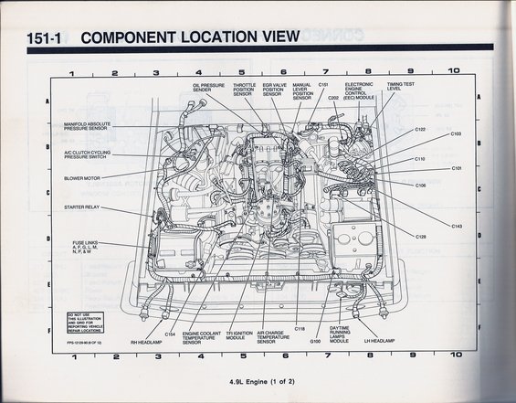
Ford EVTM component location view 151-1 for the 4.9L engine; maps ECT, ACT, TPS, MAP, EGR position sensor, EEC module, TFI and connectors C100-C154 by grid zone.
This is page 151-1, "Component Location View," from a Ford factory wiring/EVTM-style manual, scanned from a 1990 Ford Bronco owner's document set. It shows an overhead line-drawing of the engine compartment for the 4.9L engine (sheet 1 of 2), overlaid with a locator grid (columns 1-10, rows A-F). Labeled components include the oil pressure sender, throttle position sensor, EGR valve position sensor, manual lever position sensor, electronic engine control (EEC) module, timing test level, manifold absolute pressure sensor, A/C clutch cycling pressure switch, blower motor, starter relay, engine coolant temperature sensor, TFI ignition module, air charge temperature sensor, daytime running lamps module, both headlamps, and ground G100. Fuse links A, F, G, L, M, N, P, and W are located near the starter relay area. Numerous harness connectors are called out: C101, C103, C106, C110, C118, C122, C128, C143, C151, C154, and C202. A boxed note warns not to use the illustration and grid for reporting vehicle repair locations. The form number FPS-12129-90 (6 of 12) dates the document to 1990. Readers can use this page to locate underhood sensors, modules, relays, fuse links, and connector positions on a 4.9L (300 I6) engine.
Is this accurate? Sign in to help verify it.
Frequently asked questions
- Where are the fuse links located on the 1990 4.9L engine?
- The diagram shows fuse links A, F, G, L, M, N, P, & W on the driver side of the engine compartment, near the starter relay (around grid area D-2/D-3).
- What connectors are identified in this component location view?
- Connectors C101, C103, C106, C110, C118, C122, C128, C143, C151, C154, and C202 are called out, along with ground G100.
- Where is the EEC module shown?
- The Electronic Engine Control (EEC) module is called out at the top right of the engine compartment view, near connector C202 and the timing test level.
- Which engine sensors are located in this diagram?
- It locates the oil pressure sender, throttle position sensor, EGR valve position sensor, manual lever position sensor, manifold absolute pressure sensor, engine coolant temperature sensor, air charge temperature sensor, plus the TFI ignition module and A/C clutch cycling pressure switch.
- Can the grid on this diagram be used for reporting repair locations?
- No. A boxed note states: 'Do not use this illustration and grid for reporting vehicle repair locations.'
Comments
More from this build














No comments yet.