1990 Ford Bronco Component Location View 151-8 - Behind Dash Connectors
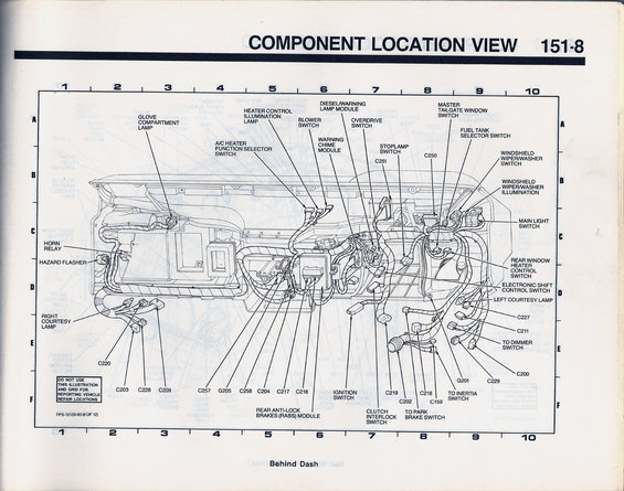
Component location view behind the dash identifying switches, relays, control modules, and connector numbers for the vehicle wiring.
This is page 151-8 of a Ford electrical vanline/EVTM-style reference, titled "Component Location View: Behind Dash." It presents a detailed line-art illustration of the dashboard area (viewed from behind) with a lettered/numbered locator grid (columns 1-10, rows A-F). Callouts identify the physical locations of electrical components and connectors behind the dash, including the glove compartment lamp, heater control illumination lamp, blower switch, A/C heater function selector switch, diesel/warning lamp module, overdrive switch, warning chime module, stoplamp switch, master tailgate window switch, fuel tank selector switch, windshield wiper/washer switch and its illumination, main light switch, horn relay, hazard flasher, rear window heater control switch, electronic shift control switch, left and right courtesy lamps, ignition switch, rear anti-lock brakes (RABS) module, and clutch interlock switch. Numbered connectors and grounds are also located: C159, C200, C202, C203, C204, C209, C211, C216, C217, C218, C219, C220, C227, C228, C229, C250, C251, C257, C258, plus grounds G201 and G205, and references to the dimmer switch, park brake switch, and inertia switch. The figure is identified as FPS-12129-90 (8 of 12), with a note that the illustration/grid is not to be used for reporting vehicle repair locations. This helps a reader physically locate wiring connectors and switches behind a 1990 Bronco's dash.
Is this accurate? Sign in to help verify it.
Frequently asked questions
- What area of the vehicle does the 151-8 component location view cover?
- It shows the "Behind Dash" area, illustrating the locations of switches, modules, lamps, connectors, and grounds behind the dashboard.
- Where is the RABS module located?
- The Rear Anti-Lock Brakes (RABS) module is shown behind the dash, called out in the lower-center area of the illustration (around grid columns 5-6).
- Which connector numbers are identified behind the dash in this diagram?
- C159, C200, C202, C203, C204, C209, C211, C216, C217, C218, C219, C220, C227, C228, C229, C250, C251, C257, and C258, plus grounds G201 and G205.
- Are the horn relay and hazard flasher shown on this page?
- Yes, both the horn relay and hazard flasher are called out on the left side of the behind-dash illustration (around grid rows C-D).
- Can the grid on this illustration be used to report repair locations?
- No. The document explicitly states: "DO NOT USE THIS ILLUSTRATION AND GRID FOR REPORTING VEHICLE REPAIR LOCATIONS."
Comments
More from this build














No comments yet.