1990 Ford Bronco Frame Rail Component Location View 151-11 - Connectors & Sensors

Reference · 1987-1991 BroncoAll 111 schematics


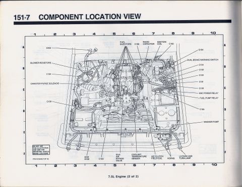












Component location view (frame rail) identifying speed sensor, ABS sensors, fuel pumps, turn/stop lamps, and connector callouts.
Part of 1987-1991 Ford Bronco Schematics
This is page 151-11 of a Ford component location manual (drawing FPS-12129-90, sheet 11 of 12), showing a "Frame Rail View", an exploded-style illustration of the vehicle's frame/chassis with its wiring harness routing. A lettered/numbered grid (columns 1-10, rows A-F) surrounds the drawing for locating components. Callout arrows identify the physical positions of electrical connectors and components along the frame rails, including connectors C101, C102, C106, C113, C114, C117, C122, C129, C134, C143, C158, C400, C401, C407, C408, C410, C414, C417, and ground G401. Named components include the E40D transmission connector, HEGO (oxygen) sensor, manual lever position sensor, rear anti-lock valve assembly, ABS rear axle sensor, vehicle speed sensor, fuel tank selector valve, 4x4 indicator switch, fuel gauge sender/electric fuel pump, fuel gauge sender and pump, license lamp, and left and right rear turn/stop lamps. A note warns not to use the illustration and grid for reporting vehicle repair locations. The "-90" suffix in the drawing number indicates a 1990 model-year document, consistent with the uploader's 1990 Ford Bronco. A reader can use this page to physically locate underbody connectors and components referenced in the associated wiring schematics.
Is this accurate? Sign in to help verify it.
Frequently asked questions
- Where is the ABS rear axle sensor shown on the 1990 frame rail diagram?
- The ABS rear axle sensor is called out near the rear of the frame, with the arrow pointing toward the rear axle area around grid columns 6-7. The rear anti-lock valve assembly is separately called out toward the front-left of the frame.
- Which connectors are located at the rear of the frame near the tail lamps?
- The rear area callouts include C143, C408 (near the right rear turn/stop lamps), C400, C401, C407, C410, C417, ground G401, the license lamp, and the left rear turn/stop lamps.
- What fuel system components appear on this frame rail view?
- The fuel tank selector valve, the fuel gauge sender/electric fuel pump, and the fuel gauge sender and pump are all called out, along with connector C414.
- Does this diagram show the vehicle speed sensor location?
- Yes, the vehicle speed sensor is called out on the frame near the transmission area, close to the C158 connector callout.
- What is the drawing number of this component location view?
- The drawing is identified as FPS-12129-90 (11 of 12), page 151-11, titled 'Frame Rail View'.






No comments yet.