Home/
Registry/
Ford/
Bronco/
1992-1996/
“pukin' dogII”/
Photo
supermotors.net/registry/media/877810
1996 Ford Bronco Instrument Cluster Connector C1 Pinout Diagram (14-Pin)

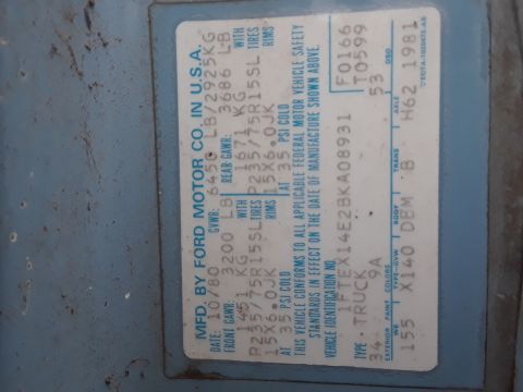
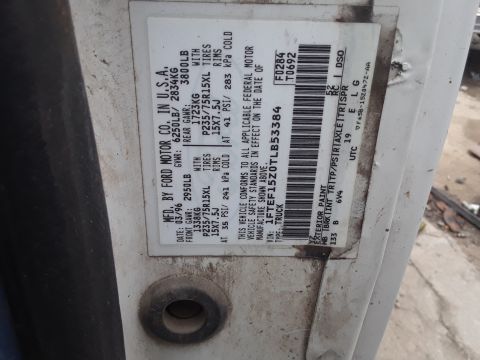
Reference · 1992-1996 BroncoAll 103 data & spec plates

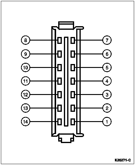









Electrical connector pinout diagram showing a 14-cavity connector with pins numbered 1 through 14.
Part of 1992-1996 Ford Bronco Data & Spec Plates
This document is a line-art connector face diagram identified by the Ford illustration number K20271-C. It depicts a 14-cavity electrical connector viewed from the mating face, with a center keyway rib and a locking tab at the top. The fourteen pin cavities are arranged in two vertical columns of seven, with callout leader lines labeling each cavity: pins 8 through 14 run top-to-bottom on the left column, and pins 7 through 1 run top-to-bottom on the right column (pin 1 at bottom right, pin 14 at bottom left). According to the uploader's filename, this represents connector C1 of the instrument cluster on a 1996 Ford Bronco. The diagram itself contains no wire colors, circuit numbers, or signal descriptions, only the physical cavity numbering. A reader can use this diagram to correctly identify pin locations when probing or back-probing the instrument cluster connector during electrical diagnosis, ensuring measurements are taken at the intended cavity. It would typically be used alongside a wiring diagram or pinout table that assigns circuits to each numbered position.
Is this accurate? Sign in to help verify it.
Frequently asked questions
- How many pins does this connector have?
- The connector shown has 14 pin cavities, arranged in two vertical columns of seven.
- How are the pins numbered on this connector?
- Viewed from the face shown, pins 8 through 14 run top to bottom on the left column, and pins 7 through 1 run top to bottom on the right column (pin 1 is at the bottom right).
- Does this diagram show wire colors or circuit functions?
- No. It only shows the physical pin numbering of the 14-cavity connector; no wire colors, circuits, or functions are listed.
- What is the illustration reference number on this diagram?
- The diagram carries the reference number K20271-C in the lower right corner.






No comments yet.