Home/
Registry/
Ford/
Bronco/
1992-1996/
“pukin' dogII”/
Photo
supermotors.net/registry/media/877816
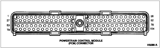
1996 Ford Bronco PCM Connector Pinout Diagram - 104-Pin Numbering (V9286-A)
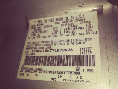
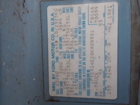
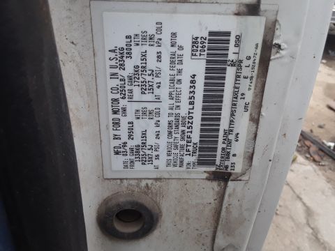
Reference · 1992-1996 BroncoAll 103 data & spec plates

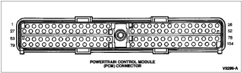









Powertrain Control Module (PCM) connector pinout diagram showing the 104-cavity layout with corner pin numbers.
Part of 1992-1996 Ford Bronco Data & Spec Plates
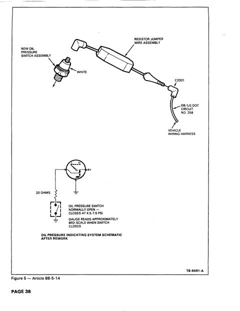
This document is a line-art illustration of the Powertrain Control Module (PCM) connector, showing the connector face as viewed with its 104 pin cavities arranged in four horizontal rows. Numeric callouts on the left edge identify the first pin of each row (1, 27, 53, and 79), and callouts on the right edge identify the last pin of each row (26, 52, 78, and 104), allowing a reader to determine the physical location of any pin number from 1 through 104. A central circular feature (the connector's bolt/fastener hole) is shown in the middle of the connector body, along with locking tabs along the top and bottom edges. The drawing carries the Ford illustration reference number V9286-A. The document itself contains no wiring colors, circuit numbers, or pin function assignments, it serves purely as a physical pin-numbering/orientation reference for the 104-pin PCM connector. It was uploaded to a 1996 Ford Bronco gallery as "96PCMconnectorPinOut.gif," which is consistent with the 104-pin EEC-V PCM connector used on that vehicle, though the drawing itself states no year, make, or model.
Is this accurate? Sign in to help verify it.
Frequently asked questions
- How many pins does this PCM connector have?
- The diagram shows a 104-pin connector, with row-end callouts numbered 1, 27, 53, and 79 on the left and 26, 52, 78, and 104 on the right.
- How are the pins numbered on the PCM connector?
- Pins are numbered in four horizontal rows: row 1 runs from pin 1 to 26, row 2 from 27 to 52, row 3 from 53 to 78, and row 4 from 79 to 104.
- Does this diagram show what each PCM pin does or its wire color?
- No. The diagram only shows the physical layout and numbering of the connector cavities; it lists no pin functions, circuits, or wire colors.
- What is the reference number on this illustration?
- The drawing is marked V9286-A.






No comments yet.