Home/
Registry/
Ford/
Bronco/
1992-1996/
“pukin' dogII”/
Photo
supermotors.net/registry/media/877809
Ford Fuel Injector Cutaway Diagram - Bosch EV1.3C, Nippondenso TOSK II, Bosch EV6

Reference · 1992-1996 BroncoAll 169 exploded parts diagrams
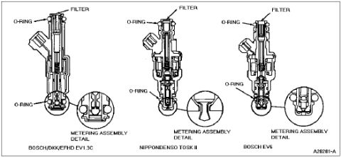
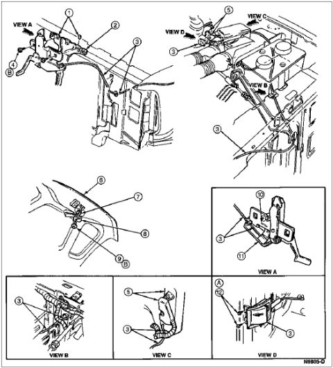
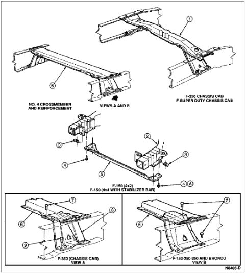
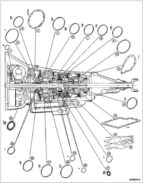
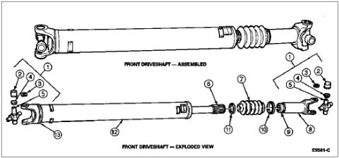





Fuel injector cross-section detail comparing Bosch EV1.3C, Nippondenso TOSK II and Bosch EV6 units with O-ring, filter and metering-assembly callouts.
Part of 1992-1996 Ford Bronco Exploded Parts Diagrams
This document is a technical illustration showing cross-sectional (cutaway) diagrams of three different fuel injector designs used in Ford vehicles. Three injector styles are shown side by side: the Bosch/DKK/EFHD EV1.3C, the Nippondenso TOSK II, and the Bosch EV6. Each injector diagram is labeled with callouts identifying the inlet filter at the top and the O-rings at the top and bottom sealing surfaces. Each injector also has an enlarged inset circle labeled 'Metering Assembly Detail' showing a close-up of the pintle/metering tip at the bottom of the injector, illustrating the differences in spray tip construction among the three designs. The figure carries the Ford illustration reference number A26281-A. This diagram would help a reader identify which style of fuel injector is installed in their vehicle, locate the O-ring positions for replacement during injector service, and understand the internal construction differences between the Bosch EV1.3C, Nippondenso TOSK II, and Bosch EV6 injector families. The document itself does not state a specific model year, vehicle model, or engine application; it was uploaded as reference material for a 1996 Ford Bronco.
Is this accurate? Sign in to help verify it.
Frequently asked questions
- What fuel injector types are shown in this diagram?
- Three injector designs are illustrated: the Bosch/DKK/EFHD EV1.3C, the Nippondenso TOSK II, and the Bosch EV6.
- Where are the O-rings located on these fuel injectors?
- Each injector has two O-rings, one near the top of the injector body below the filter and one at the bottom near the metering tip.
- Where is the filter on these fuel injectors?
- The filter is located at the top (inlet end) of each injector, as shown by the FILTER callout on all three designs.
- What does the circled inset on each injector show?
- Each inset circle is labeled 'Metering Assembly Detail' and shows a magnified view of the metering/spray tip at the bottom of that injector.
- What is the Ford illustration reference number for this diagram?
- The figure is marked A26281-A.






No comments yet.