Home/
Registry/
Ford/
Bronco/
1992-1996/
“pukin' dogII”/
Photo
supermotors.net/registry/media/877815
Ford Bronco/F-Series 14B080 Battery Cable Assembly Routing Diagram (K20713-C)

Reference · 1992-1996 BroncoAll 169 exploded parts diagrams
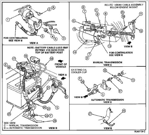
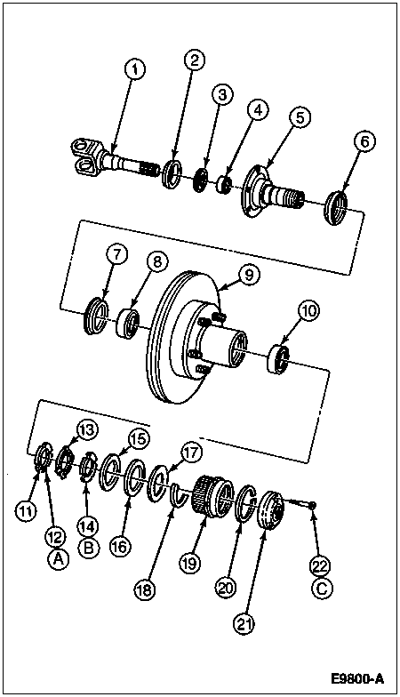
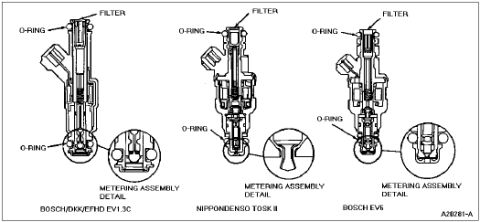
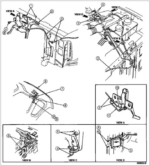
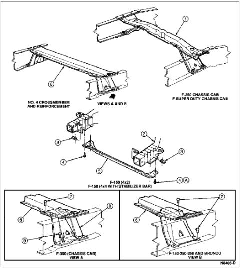





Exploded battery-cable diagram with multiple views showing cable lug connections and routing for manual and automatic transmission vehicles.
Part of 1992-1996 Ford Bronco Exploded Parts Diagrams
This is an exploded parts / routing illustration for a battery cable and wiring harness assembly, identified by Ford illustration number K20713-C. The instruction at the top directs the installer to route the 14B080 cable assembly below the engine mount. The document is divided into five views: View A shows the cable connections at the starter/engine area with callouts 1-5 and connector points labeled A, continuing into View B. View B (lower left) shows the battery, battery cables, and harness routing at the front of the vehicle (callouts 5, 16-25, E, F), with a note that battery cable lugs may extend 1/16 inch over the top of the battery post. View C details the manual transmission routing (callouts 3-15, B, C, D) with continuation to View E. View D shows the automatic transmission routing at the existing oil cooler cup (callouts 5, 6, 11, 12, 17, 26, F). View E shows callouts 15 and 27. A legend keys View C to manual transmissions and View D to automatic transmissions. No year, model, or itemized parts list appears on this page; the callout numbers presumably reference a separate legend.
Is this accurate? Sign in to help verify it.
Frequently asked questions
- Where should the 14B080 cable assembly be routed?
- The diagram instructs to route the 14B080 cable assembly below the engine mount.
- Is there a note about battery cable lug fitment?
- Yes: the note states that battery cable lugs may extend 1/16 inch over the top of the battery post.
- Which views apply to manual vs. automatic transmissions?
- View C shows the manual transmission routing and View D shows the automatic transmission routing; the legend states C = manual transmission, D = automatic transmission.
- What is shown near the automatic transmission cable routing in View D?
- View D shows the cable routed at the existing oil cooler cup on automatic transmission vehicles.
- What is the Ford illustration number for this diagram?
- The illustration is marked K20713-C in the lower right corner.






No comments yet.