Home/
Registry/
Ford/
Bronco/
1992-1996/
“pukin' dogII”/
Photo
supermotors.net/registry/media/877820
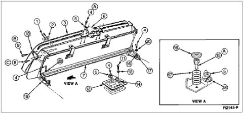
1996 Ford Bronco Rear Seat Exploded Parts Diagram (Ford R2143-P)

Reference · 1992-1996 BroncoAll 169 exploded parts diagrams
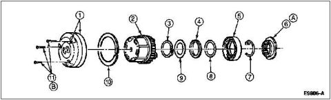
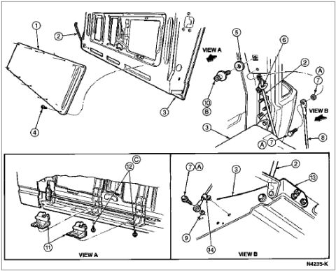
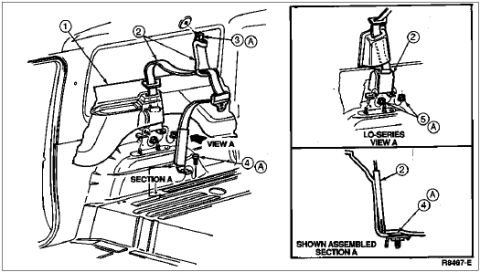
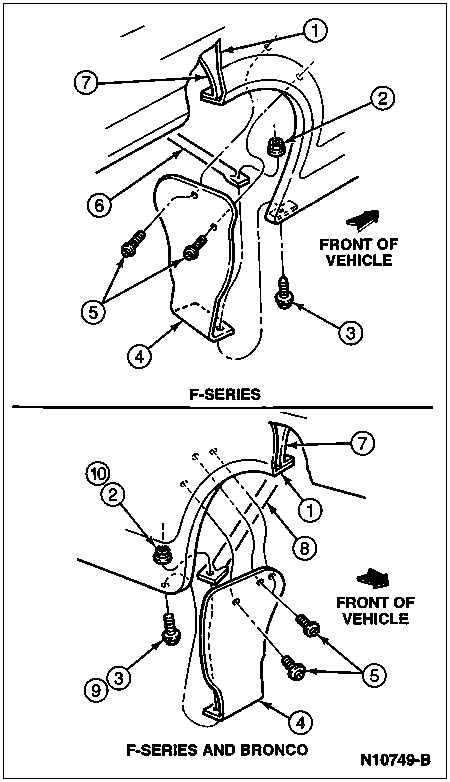
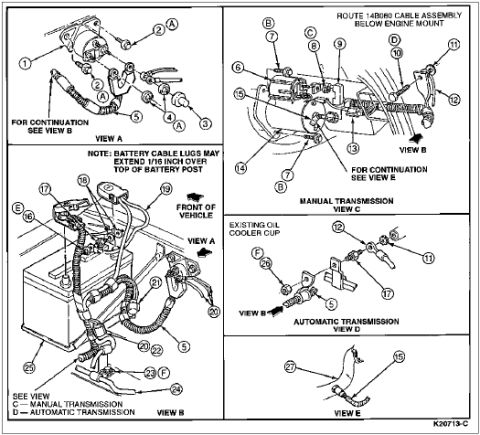
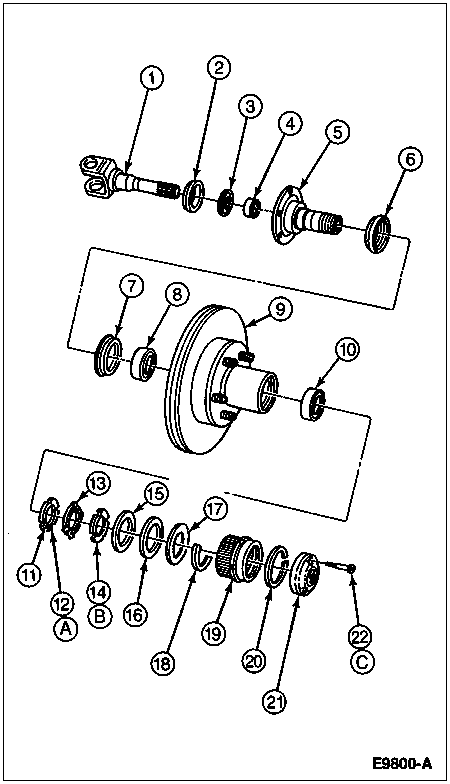
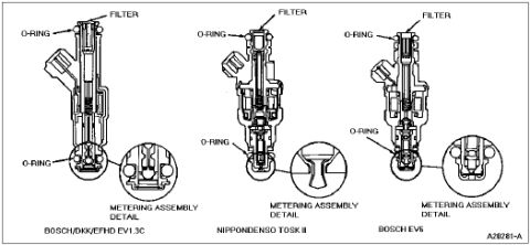




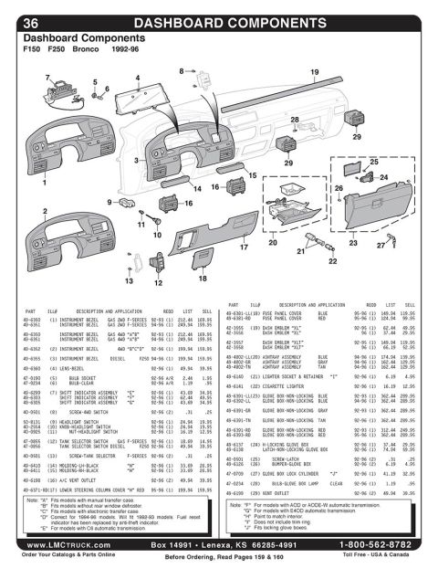

Exploded parts breakdown of a panel/console assembly with numbered hardware callouts and a mounting detail inset.
Part of 1992-1996 Ford Bronco Exploded Parts Diagrams
This document is a scanned exploded-parts illustration, apparently from a Ford factory service manual, showing a rear seat assembly (uploaded as documentation for a 1996 Ford Bronco rear seat). The main drawing depicts the rear seat back/frame assembly with numbered callouts 1 through 20 plus lettered callouts A, B, and C pointing to individual components such as brackets, fasteners, latch/pivot hardware, and a floor-mounted latch or striker assembly shown at the bottom center. A directional arrow labeled 'VIEW A' indicates the viewing angle for the enlarged detail inset at the right side of the page, which shows a close-up of a mounting/pivot assembly with callouts 15, 16, 17, and 18 (and reference letter A), illustrating how a bushing, spacer, and bracket stack together on the mounting base. The illustration carries the Ford drawing reference number R2143-P in the lower right corner. No parts legend, part numbers, torque specifications, or text descriptions of the numbered items appear on this particular scan, so a reader can learn the physical arrangement and assembly order of the rear seat components but must consult an accompanying legend page for part names and numbers.
Is this accurate? Sign in to help verify it.
Frequently asked questions
- What does this diagram show?
- It is an exploded-view illustration of a rear seat assembly with numbered callouts 1-20 and lettered callouts A, B, and C identifying individual components, plus an enlarged detail labeled VIEW A.
- What is shown in the VIEW A inset?
- VIEW A is a close-up of a mounting/pivot assembly, showing how items 15, 16, 17, and 18 stack together on the mounting base, with reference letter A also indicated.
- Does this diagram include part names or part numbers?
- No. This scan shows only the illustration with numbered callouts and the drawing reference R2143-P; no legend, part names, or part numbers are visible.
- What is the drawing reference number on this illustration?
- The reference number R2143-P appears in the lower right corner of the diagram.






No comments yet.