Home/
Registry/
Hyundai/
Genesis Coupe/
2010-2016/
“Coupe”/
Photo
supermotors.net/registry/media/878844
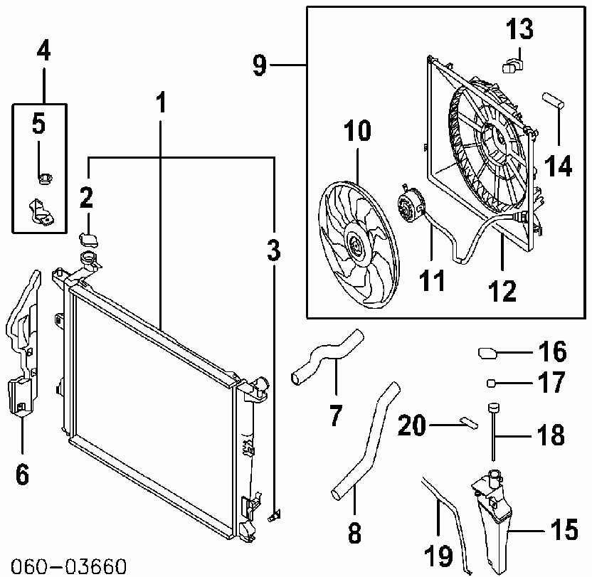
2010 Hyundai Genesis Coupe 2.0T Radiator & Cooling Fan Exploded Parts Diagram
Reference · 2010-2016 Genesis CoupeAll 14 exploded parts diagrams
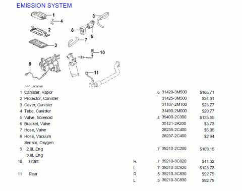
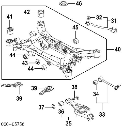
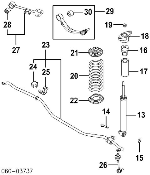
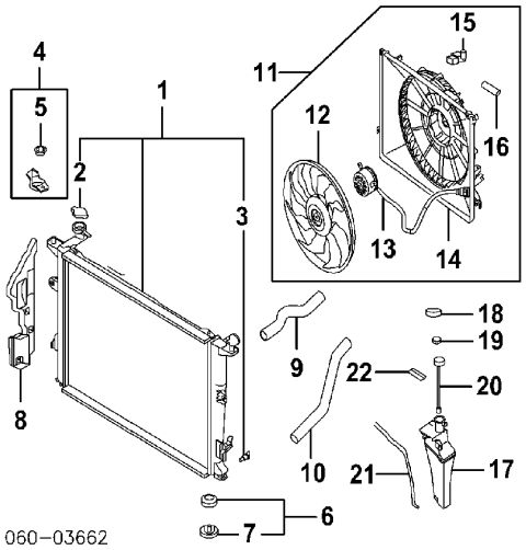
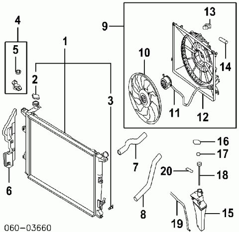








Exploded parts diagram of a cooling system showing radiator, fan, shroud, hoses, and coolant reservoir with numbered callouts.
Part of 2010-2016 Hyundai Genesis Coupe Exploded Parts Diagrams
This document is an exploded parts diagram (reference number 060-03660) of an automotive engine cooling system, showing the radiator and its related components. Twenty numbered callouts identify the individual parts: the radiator core (1), radiator cap (2), mounting brackets and fasteners (3, 4, 5), a side air guard panel (6), upper and lower radiator hoses (7, 8), the complete cooling fan shroud assembly (9) with its fan blade (10), fan motor (11), wiring harness (12), and small clips/pads (13, 14), plus the coolant overflow reservoir (15) with its cap, hose, and associated clips and plugs (16-20). The drawing contains no textual legend, part numbers (other than the diagram code), torque values, or vehicle identification, so part names must be inferred from the illustrations. It was uploaded to a 2010 Hyundai Genesis gallery with the filename '2L radiator and parts.gif,' suggesting it applies to the 2.0L engine variant (likely the Genesis Coupe 2.0T based on companion files in the album). A reader can use this diagram to see how the radiator, fan shroud, hoses, and coolant reservoir assemble together and to identify individual components by their callout numbers when cross-referencing a parts catalog legend.
Is this accurate? Sign in to help verify it.
Frequently asked questions
- What components are shown in this radiator parts diagram?
- The diagram shows the radiator core, radiator cap, mounting brackets and fasteners, a side air guard, upper and lower radiator hoses, the cooling fan shroud assembly with fan blade and motor, and the coolant overflow reservoir with its cap, hose, and clips, 20 numbered parts in total.
- Does the diagram include part numbers or torque specs?
- No. The only reference text visible is the diagram code 060-03660 at the bottom left; the callouts are numbers 1-20 with no legend, part numbers, or torque values shown.
- How is the cooling fan assembly depicted?
- The fan assembly is shown as a boxed exploded group (callout 9) containing the fan blade (10), fan motor (11), wiring harness (12), and small clips/pads (13 and 14) mounted to the shroud.
- Which callouts identify the radiator hoses?
- Callout 7 points to the upper radiator hose and callout 8 points to the lower radiator hose.
- Which item is the coolant overflow reservoir?
- Callout 15 identifies the coolant reservoir tank, with related items 16-20 covering its cap/plug, clips, cap-and-hose assembly, and overflow hose.

No comments yet.