Home/
Registry/
Hyundai/
Genesis Coupe/
2010-2016/
“Coupe”/
Photo
supermotors.net/registry/media/904599
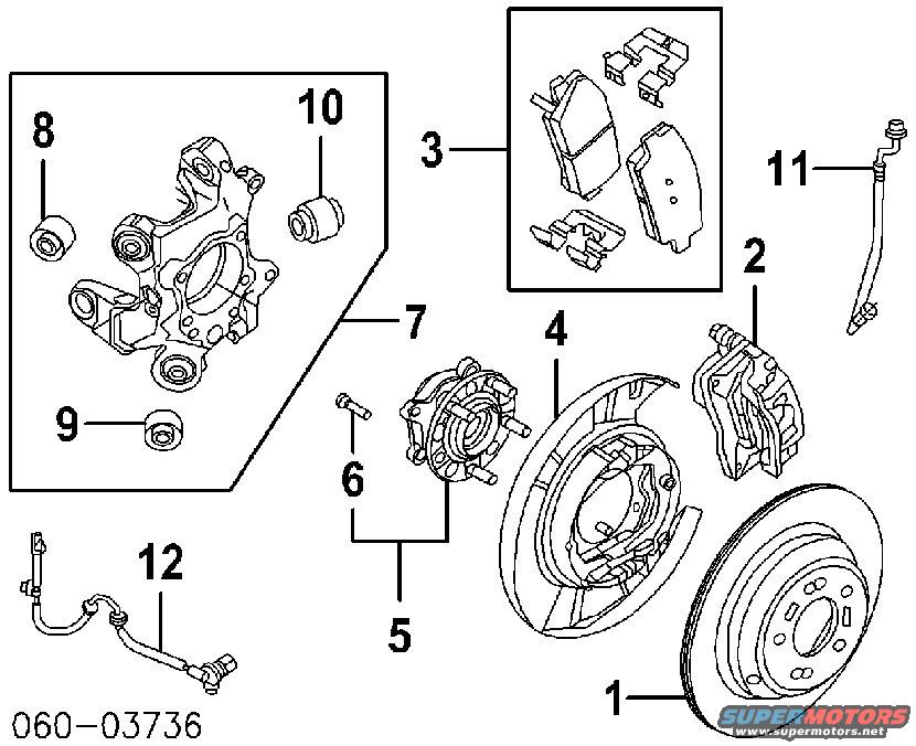
2010 Hyundai Genesis Coupe Rear Brake & Knuckle Exploded Parts Diagram
Reference · 2010-2016 Genesis CoupeAll 14 exploded parts diagrams
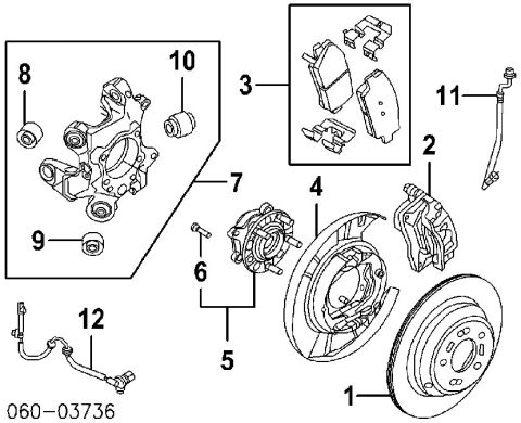








Exploded parts diagram of a rear brake assembly showing knuckle, hub, rotor, caliper, brake pads, and ABS sensor.
Part of 2010-2016 Hyundai Genesis Coupe Exploded Parts Diagrams
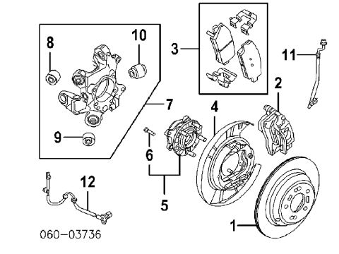
This document is an exploded parts diagram of a rear brake and rear knuckle/hub assembly, uploaded to the gallery of a 2010 Hyundai Genesis Coupe. The diagram contains twelve numbered callouts identifying components: the ventilated rear brake rotor (1), brake caliper (2), a boxed brake pad kit with shims and clips (3), the parking-brake backing plate/dust shield (4), the hub and wheel bearing assembly (5) with its mounting bolt (6), the rear knuckle assembly (7) shown in a boxed inset with three press-in bushings (8, 9, 10), the flexible brake hose (11), and the ABS wheel speed sensor with its harness (12). The only printed text on the diagram is the figure/reference number "060−03736" in the lower-left corner; no part numbers, torque values, model names, or years are printed on the image. A reader can learn how the rear brake components relate to one another and the order of assembly, rotor onto hub, hub bolted into the knuckle, backing plate between hub and rotor, caliper and pads over the rotor, with the brake hose and ABS sensor attaching to the assembly, which is useful for planning rear brake, wheel bearing, or knuckle bushing service.
Is this accurate? Sign in to help verify it.
Frequently asked questions
- What components are shown in this rear suspension/brake exploded diagram?
- Twelve numbered items: rear brake rotor (1), caliper (2), brake pad kit with hardware (3), parking brake backing plate/dust shield (4), hub and bearing assembly (5), hub bolt (6), rear knuckle (7), three knuckle bushings (8, 9, 10), brake hose (11), and ABS wheel speed sensor (12).
- Does the diagram show the rear knuckle bushings?
- Yes. The boxed inset labeled 7 shows the rear knuckle, and items 8, 9, and 10 identify three separate bushings that press into it.
- Is the rear wheel hub a separate assembly from the knuckle?
- Yes. Item 5 is the hub and wheel bearing assembly, shown as a unit that bolts (item 6) to the knuckle (item 7).
- Is the ABS wheel speed sensor included in this diagram?
- Yes, item 12 shows the wheel speed sensor with its wiring harness and mounting bracket.
- Are any part numbers or torque specs printed on this diagram?
- No. The only printed text is the figure reference "060−03736"; no part numbers, torque values, or amperages appear.

No comments yet.