Home/
Registry/
Hyundai/
Genesis Coupe/
2010-2016/
“Coupe”/
Photo
supermotors.net/registry/media/1139726
2010 Hyundai Genesis Coupe BCM Connector M02-D Pinout Diagram

Reference · 2010-2016 Genesis CoupeAll 79 wiring diagrams

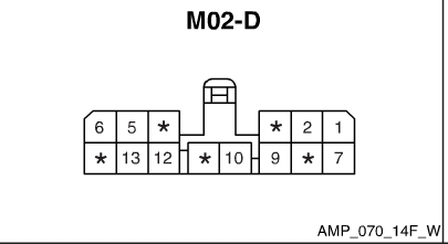








Connector terminal pinout for connector M02-D with numbered and unused cavity positions.
Part of 2010-2016 Hyundai Genesis Coupe Wiring Diagrams
This document is a connector pinout illustration labeled "M02-D", uploaded as part of a wiring diagram set for a 2010 Hyundai Genesis (Genesis Coupe, per album context). The drawing shows the face view of a multi-pin electrical connector with a locking tab at the top center. The connector has two rows of terminal cavities. The top row shows numbered positions 6, 5, and an unnumbered position (marked with an asterisk) on the left side, and an asterisk, 2, and 1 on the right side of the latch gap. The bottom row shows an asterisk, 13, 12, asterisk, 10, 9, asterisk, and 7. Asterisks indicate cavities without assigned or populated circuits. The connector housing style reference "AMP_070_14F_W" appears in the lower right corner, likely identifying the connector series/housing type (AMP 070-series, 14-position female, white). A reader can use this diagram to identify pin cavity numbering when probing or repairing the M02-D connector, which per the uploader's filename connects to the BCM (Body Control Module). The document contains no wire colors, circuit descriptions, year, model, or part numbers beyond the connector housing code.
Is this accurate? Sign in to help verify it.
Frequently asked questions
- What connector is shown in this diagram?
- Connector M02-D, illustrated as a two-row connector with a latch at the top center and housing reference AMP_070_14F_W.
- Which pin numbers are labeled on connector M02-D?
- The top row shows pins 6, 5, 2, and 1; the bottom row shows pins 13, 12, 10, 9, and 7. Positions marked with an asterisk (*) are unnumbered/unassigned cavities.
- What does the code AMP_070_14F_W mean in the diagram?
- It is the reference code printed at the lower right of the diagram identifying the connector housing type; the document itself does not explain the code further.
- Does this diagram show wire colors or circuit functions?
- No. It only shows the connector cavity numbering layout; no wire colors, circuit names, or functions are listed.

No comments yet.