Home/
Registry/
Ford/
Bronco/
1992-1996/
1996 Ford Bronco/
Photo
supermotors.net/registry/media/908101
1996 Ford Bronco & F-150/250/350 Instrument Cluster Diagram - Warning Lights

Reference · 1992-1996 BroncoAll 98 manual pages
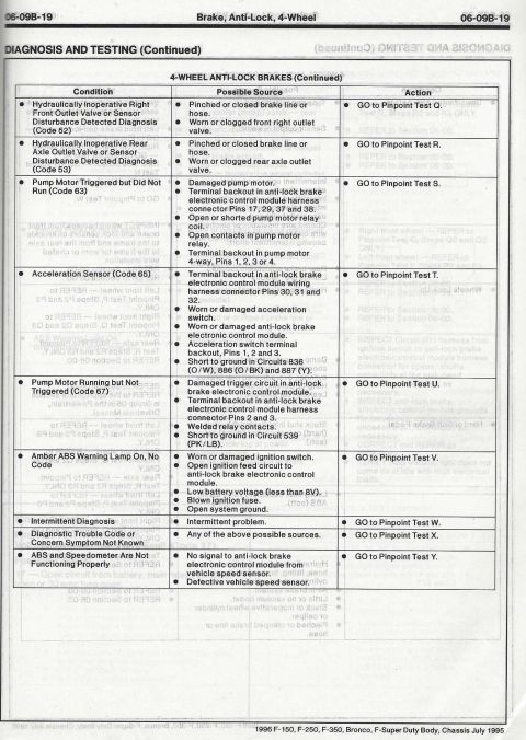
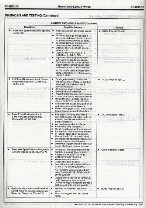
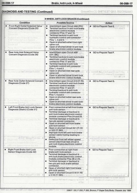
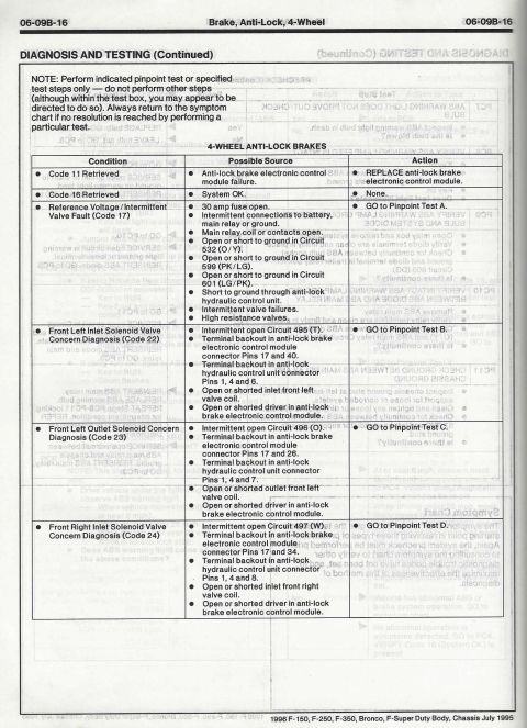
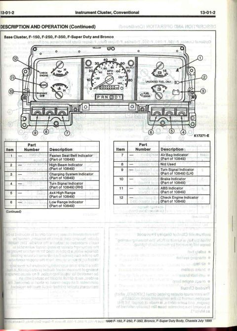
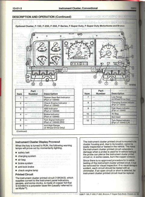






Service manual description-and-operation page for the optional instrument cluster with labeled diagram and part-number table.
Part of 1992-1996 Ford Bronco Manual Pages
This is page 13-01-3 from the 1996 Ford F-150, F-250, F-350, Bronco, and F-Super Duty Body/Chassis service manual (dated July 1995), covering the conventional instrument cluster, section 'Description and Operation (Continued).' It shows an exploded diagram (K17273-E) of the optional instrument cluster for F-150, F-250, F-350, F-Series, F-Super Duty, F-Super Duty Motorhome, and Bronco, with 12 numbered callouts identified in two legend tables. Indicators include the Fasten Seat Belt, Check Engine, ABS, Brake, RH and LH Turn Signal, 4x4 High Range and Low Range (4-wheel drive only), Charging System, High Beam, and Air Bag indicators; position 11 is Not Used. Most warning lamps are noted as part of the cluster assembly (10849). The page also explains the Instrument Cluster Display Proveout: when the key is turned to RUN, the safety belt, charging system, air bag, brake system, anti-lock brake, and check engine lamps momentarily light. A section on the printed circuit (10K843) explains it is copper foil bonded to a Mylar polyester film, cannot be safely probed in-vehicle, must be removed for visual inspection, and should be tested with an ohmmeter, being replaced if any open or short is found.
Is this accurate? Sign in to help verify it.
Frequently asked questions
- What do the numbered indicators on the 1996 Ford Bronco/F-Series optional instrument cluster mean?
- Per the legend: 1 Fasten Seat Belt, 2 Check Engine, 3 ABS, 4 Brake, 5 Turn Signal (RH), 6 4x4 High Range (4WD only), 7 Low Range (4WD only), 8 Charging System, 9 High Beam, 10 Air Bag, 11 Not Used, 12 Turn Signal (LH). Most are listed as part of 10849.
- Which warning lamps prove out when the key is turned to RUN?
- The safety belt, charging system, air bag, brake system, anti-lock brake, and check engine lamps momentarily light when the key is turned to RUN.
- Can the instrument cluster printed circuit be tested in the vehicle?
- No. There is no approved procedure for in-vehicle testing; probing can pierce the printed circuit or burn the copper conductor. It must be removed for visual inspection and each circuit tested with an ohmmeter. If an open or short is found, the printed circuit must be replaced.
- What is the instrument cluster printed circuit made of?
- The printed circuit (10K843) is made of copper foil bonded to a polyester base film, usually referred to as Mylar®.
- Which vehicles does this instrument cluster page apply to?
- The 1996 F-150, F-250, F-350, F-Series, F-Super Duty, F-Super Duty Motorhome, and Bronco (optional cluster).






No comments yet.