Home/
Registry/
Ford/
Bronco/
1992-1996/
1996 Ford Bronco/
Photo
supermotors.net/registry/media/908102
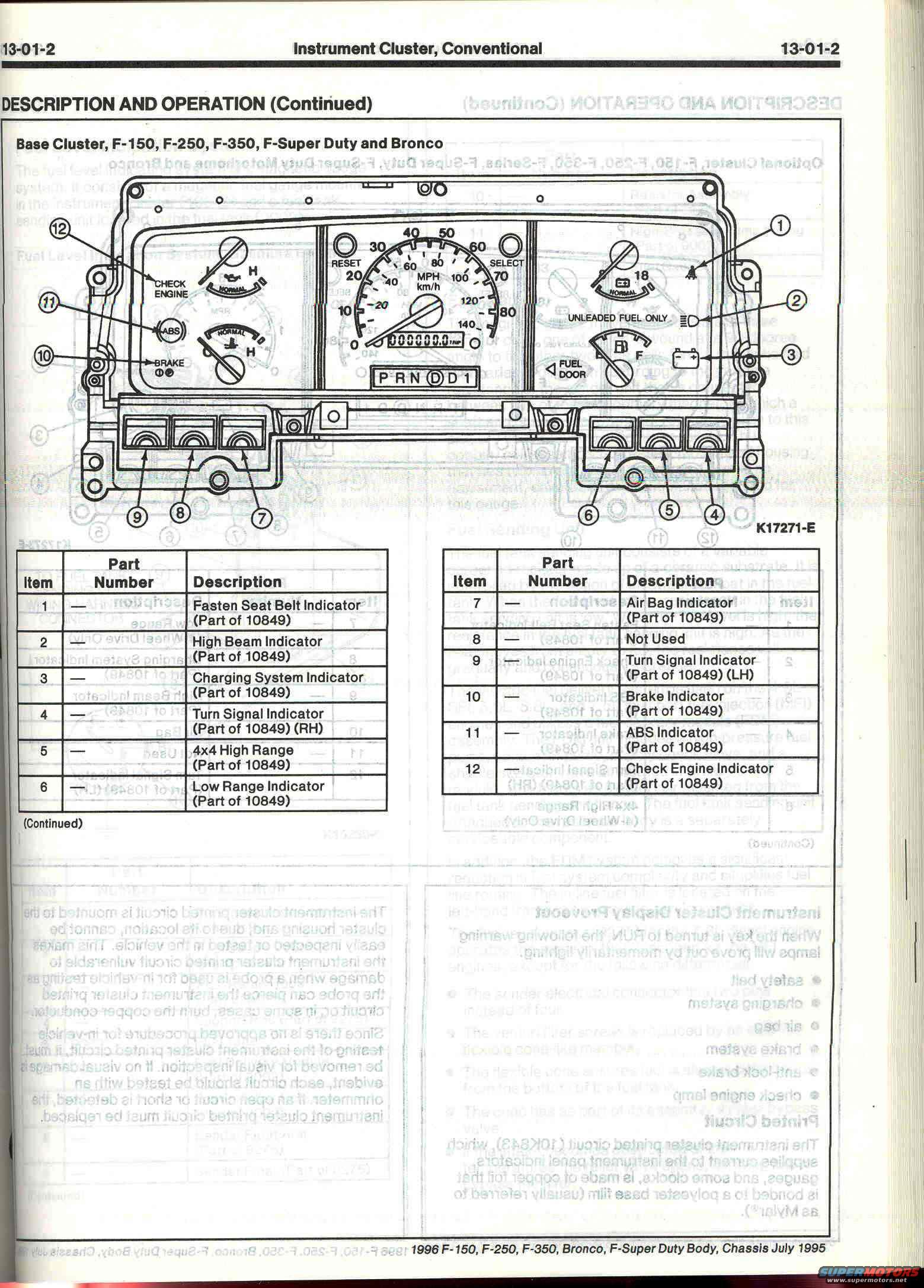
1996 Ford Bronco/F-150 Instrument Cluster Indicator Diagram - Page 13-01-2
Reference · 1992-1996 BroncoAll 98 manual pages
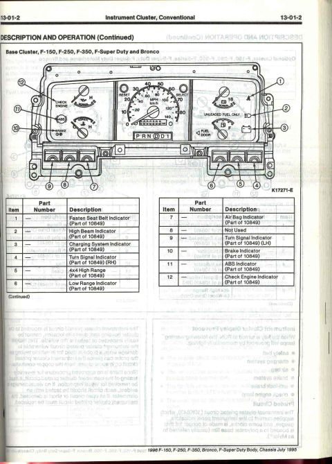








Service manual description-and-operation page for the base instrument cluster with labeled diagram and part-number table.
Part of 1992-1996 Ford Bronco Manual Pages
This is page 13-01-2 from the 1996 Ford F-150/F-250/F-350/Bronco/F-Super Duty Body and Chassis service manual (dated July 1995), covering the Conventional Instrument Cluster in the Description and Operation section. The page presents an exploded illustration (figure K17271-E) of the Base Cluster used in the F-150, F-250, F-350, F-Super Duty and Bronco, with twelve numbered callouts identifying the warning indicator locations in the cluster. An accompanying two-part legend table identifies each item: (1) Fasten Seat Belt Indicator, (2) High Beam Indicator, (3) Charging System Indicator, (4) Turn Signal Indicator RH, (5) 4x4 High Range, (6) Low Range Indicator, (7) Air Bag Indicator, (8) Not Used, (9) Turn Signal Indicator LH, (10) Brake Indicator, (11) ABS Indicator, and (12) Check Engine Indicator: all noted as 'Part of 10849' (the instrument cluster assembly). The illustration also shows the tachometer, 0-140 MPH speedometer, trip odometer, PRNDD1 shift indicator, oil pressure, temperature, voltage and fuel gauges, and the 'UNLEADED FUEL ONLY' and 'FUEL DOOR' markings. Reverse-side text bleeding through describes the cluster display proveout and the printed circuit (part 10K843).
Is this accurate? Sign in to help verify it.
Frequently asked questions
- What warning indicators are in the 1996 Ford Bronco/F-150 base instrument cluster?
- The base cluster includes: Fasten Seat Belt, High Beam, Charging System, Turn Signal (RH and LH), 4x4 High Range, Low Range, Air Bag, Brake, ABS, and Check Engine indicators. Item 8 is listed as 'Not Used'. All indicators are noted as Part of 10849 (the cluster assembly).
- Which vehicles does this base instrument cluster diagram cover?
- The diagram is labeled 'Base Cluster, F-150, F-250, F-350, F-Super Duty and Bronco', from the 1996 F-150, F-250, F-350, Bronco, F-Super Duty Body/Chassis manual (July 1995).
- Do the individual warning lamps in the cluster have separate part numbers?
- No. The table shows no individual part numbers for the indicators, each is listed as 'Part of 10849', meaning they are part of the instrument cluster assembly.
- What gauges and features are shown on the base cluster illustration?
- The illustration shows a tachometer, a speedometer reading 0-140 MPH (with km/h), a trip odometer with RESET and SELECT buttons, oil pressure and temperature gauges marked NORMAL/H, a voltmeter, a fuel gauge (E-F) with FUEL DOOR arrow, the PRNDD1 gear indicator, and an 'UNLEADED FUEL ONLY' marking.






No comments yet.