Home/
Registry/
Ford/
Bronco/
1992-1996/
1996 Ford Bronco/
Photo
supermotors.net/registry/media/892808
Ford Automatic Transmission Exploded Parts Diagram - 1996 Bronco Reference

Reference · 1992-1996 BroncoAll 169 exploded parts diagrams
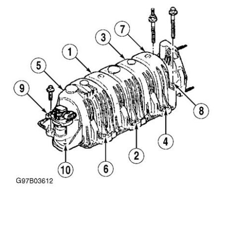
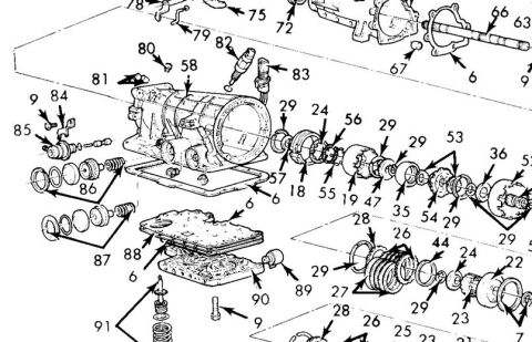
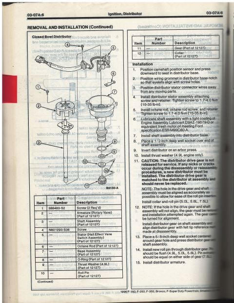
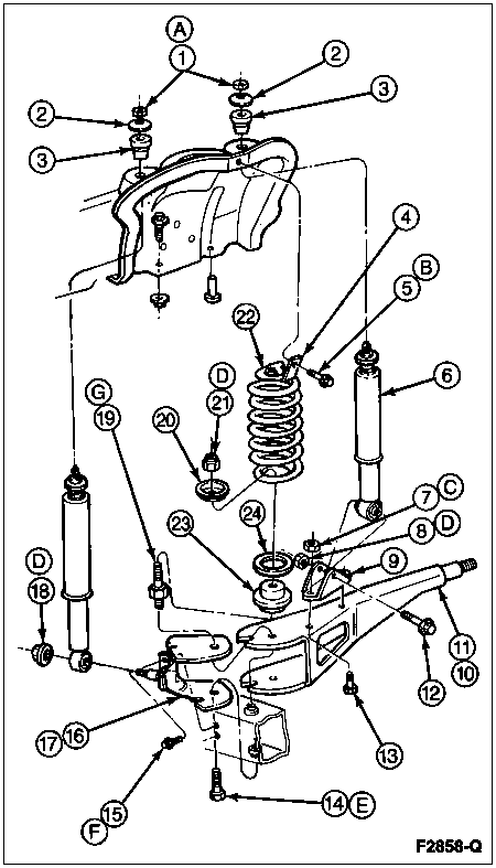

Exploded parts breakdown of an automatic transmission showing numbered internal components in assembly order.
Part of 1992-1996 Ford Bronco Exploded Parts Diagrams
This document is a cropped scan of an exploded-view parts diagram of an automatic transmission assembly. It shows the main transmission case with bellhousing, valve body, filter/screen, pan gasket, extension housing components, output shaft, servos, accumulator pistons, clutch drums, planetary gear components, seals, bushings, springs, and various small hardware, all identified only by numeric callout labels (e.g., 6, 9, 18, 19, 21-29, 35, 36, 44, 47, 52-58, 66, 67, 72, 75, 79-91). No legend or parts list keying the numbers to part names or part numbers appears in this scan, so the reader can see the physical relationship and assembly order of the components but cannot identify parts by name from this page alone. The scan contains no visible year, make, model, or engine applicability statements. It was uploaded to a 1996 Ford Bronco gallery under the filename "trans exploded.JPG," and nothing in the image contradicts that attribution, though the actual application cannot be confirmed from the visible content. A companion legend page (likely part of a multi-page set) would be required to interpret the numbered callouts.
Is this accurate? Sign in to help verify it.
Frequently asked questions
- What does this diagram show?
- An exploded view of an automatic transmission assembly, including the case, valve body, filter, pan area, servos, clutch/drum components, output shaft parts, and related seals and hardware, all labeled with numeric callouts.
- Does the diagram include a parts legend or part numbers?
- No. Only numeric callout labels (such as 6, 9, 18-29, 35, 36, 44, 47, 52-58, 66, 67, 72, 75, and 79-91) are visible; there is no legend or part number list on this page.
- Which callout numbers appear on the diagram?
- Visible numbers include 6, 9, 18, 19, 21-29, 35, 36, 44, 47, 52-58, 66, 67, 72, 75, and 79-91, with some numbers at the edges partially cut off.
- Does the document state which vehicle or year it applies to?
- No. The scan contains no visible year, make, model, or engine applicability information.



No comments yet.