1995 Ford Bronco Starting System Wiring Diagram (Page 20-1) - Ignition & CPP
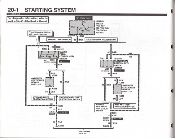
Wiring diagram for the 1995 Bronco starting system showing ignition switch, clutch pedal position switch, and anti-theft module.
This document is page 20-1 of the 1995 Ford Bronco electrical wiring diagram set, covering the Starting System. It directs readers to section 03-06 of the Service Manual for diagnostic information and to page 149-2 for ignition switch testing. The diagram traces the starting circuit from the ignition switch (hot at all times, with START/RUN/ACC/OFF/LOCK positions) through connector C269 on circuit 32 R/LB (red/light blue), then splits into two variants: manual transmission and E4OD or 4R70W automatic transmission. On manual transmission trucks, the circuit passes through the clutch pedal position (CPP) switch at connector C261, which prevents engine startup with the clutch released; automatic transmission trucks use a CPP switch jumper instead. Each branch further splits depending on whether the vehicle has the anti-theft protection system: with anti-theft, the circuit routes through the anti-theft controller module (connector C238, pins 12 and 24, circuit 342 LG/P, see page 112-2); without it, circuit 32 R/LB continues directly. Both paths pass splice S224 (circuit 480 P/Y branch) and connectors C202F/C202M before reaching C103M, continuing to C103F on page 20-2. Component location references 151-3 F4 and 151-2 A8 are provided.
This document covers 1995, which may differ from this 1990 Ford Bronco.
Is this accurate? Sign in to help verify it.
Frequently asked questions
- What wire color is the start circuit (circuit 32) on a 1995 Bronco?
- Circuit 32 is R/LB (red/light blue), carrying 12V in the START position from the ignition switch through C269 toward the starter circuit.
- How does the starting circuit differ between manual and automatic transmissions?
- Manual transmission trucks route the start signal through the Clutch Pedal Position (CPP) switch at connector C261, which prevents engine startup with the clutch released. E4OD or 4R70W automatic trucks use a CPP switch jumper at C261 instead.
- Where does the anti-theft system tie into the 1995 Bronco starting circuit?
- On vehicles with the anti-theft protection system, circuit 32 R/LB passes through the Anti-Theft Controller Module at connector C238 (pins 12 and 24), exiting on circuit 342 LG/P. Details are on page 112-2. Vehicles without anti-theft bypass this module.
- Where can I find ignition switch testing information?
- The diagram refers to page 13-3 for the ignition switch and page 149-2 for switch testing; diagnostic information is in section 03-06 of the Service Manual.
- Where does this diagram continue?
- The circuit exits through connector C103M and continues to C103F on page 20-2.
Comments
More from this build














No comments yet.