1995 Ford Bronco Anti-Theft Wiring Diagram 112-3 - Door Lock & Tamper Sensor
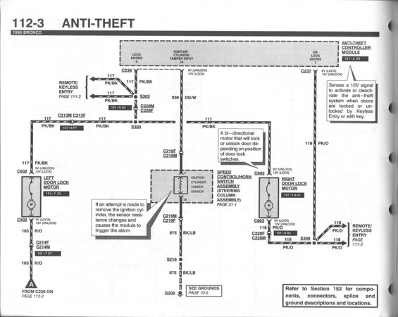
Wiring diagram for the 1995 Bronco anti-theft system showing door lock motors and ignition cylinder tamper sensor circuits.
This is page 112-3 of the 1995 Ford Bronco factory wiring diagram set (EVTM), covering the Anti-Theft system. The diagram shows the Anti-Theft Controller Module (grid reference 151-3 A4) with its Lock Doors (pin 9), Ignition Cylinder Tamper Input (pin 10), and Unlock Doors (pin 7) circuits. Circuit 117 (PK/BK wire) carries the lock signal through splices S303 and S304 and connectors C238, C228M/F, C213M/F to the left door lock motor (via C502) and right door lock motor (via C602); circuit 118 (PK/O) carries the unlock signal via C237, C228F/M and splice S306, with both circuits tying into the Remote/Keyless Entry system (page 111-2). Circuit 936 (DG/W) connects the module to the ignition cylinder tamper sensor in the speed control/horn switch assembly on the steering column (page 31-1), grounded through circuit 875 (BK/LB), splice S216, and ground G200 (see page 10-5). Notes explain that the module senses a 12V signal when doors are locked/unlocked by key or keyless entry, that the door lock motors are bi-directional, and that a resistance change in the tamper sensor triggers the alarm if the ignition cylinder is removed. Readers can trace wire colors, circuit numbers, connector IDs, and voltage states (0V/12V lock-unlock logic) for anti-theft diagnostics.
This document covers 1995, which may differ from this 1990 Ford Bronco.
Is this accurate? Sign in to help verify it.
Frequently asked questions
- What wire color and circuit number is the lock signal on a 1995 Bronco anti-theft system?
- The lock circuit is 117, a pink/black (PK/BK) wire, which shows 12V when locking and 0V when unlocking. It runs from the Anti-Theft Controller Module through C238, splices S303/S304, and connectors C228M/F and C213M/F to the door lock motors.
- What circuit does the unlock signal use?
- The unlock signal is circuit 118, pink/orange (PK/O), from the module's Unlock Doors pin 7 through connector C237, splice S306, and C228F/C228M to the right door lock motor and Remote/Keyless Entry system.
- How does the ignition cylinder tamper sensor trigger the alarm?
- If an attempt is made to remove the ignition cylinder, the sensor's resistance changes and causes the anti-theft module to trigger the alarm. The sensor connects to module pin 10 via circuit 936 (DG/W) and is grounded through circuit 875 (BK/LB) at G200.
- Which connectors serve the left and right door lock motors?
- The left door lock motor uses connector C502 (location 151-7 D1) and the right door lock motor uses C602 (location 151-7 A10). Both motors are bi-directional, locking or unlocking depending on door lock switch position.
- Where can I find connector and ground location descriptions referenced on this page?
- The diagram directs you to Section 152 for components, connectors, splice, and ground descriptions and locations; grounds are shown on page 10-5, and the keyless entry circuits continue on page 111-2.
Comments
More from this build














No comments yet.