1995 Ford Bronco Anti-Theft Wiring Diagram 112-2 - Controller Module Circuits
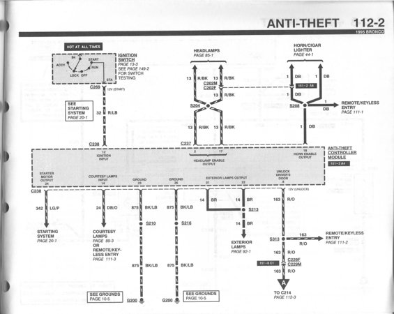
Wiring diagram for the 1995 Bronco anti-theft system showing ignition, headlamp, and remote keyless entry circuits.
This is page 112-2 of the 1995 Ford Bronco electrical vacuum troubleshooting manual (EVTM), covering the Anti-Theft system wiring. The schematic shows the Anti-Theft Controller Module (component location reference 151-3 A4) and its circuit connections. Ignition input (pin 12) comes from the ignition switch START terminal via circuit 32 R/LB through connectors C269 and C238; the switch itself is on page 13-3 with testing on page 149-2. Headlamp enable outputs (pins 2 and 17) tie into circuit 13 R/BK at splice S204 through connectors C202M/C202F and C237, leading to the headlamps (page 85-1). Horn enable output (pin 18) uses circuit 1 DB via splice S208 to the horn/cigar lighter (page 44-1) and remote/keyless entry (page 111-1). Starter motor output (pin 24) uses circuit 342 LG/P to the starting system (page 20-1). Courtesy lamps input (pin 14) is circuit 24 DB/O. Grounds (pins 23 and 26) run on circuit 875 BK/LB through splices S210 and S216 to ground G200. Exterior lamps outputs (pins 21/22) use circuit 14 BR via splice S213 to exterior lamps (page 92-1). Unlock driver's door output (pin 8) is circuit 163 R/O through splice S313 and connector C229F/C229M, continuing to C214 on page 112-3.
This document covers 1995, which may differ from this 1990 Ford Bronco.
Is this accurate? Sign in to help verify it.
Frequently asked questions
- What wire circuit provides ignition input to the 1995 Bronco anti-theft controller module?
- Circuit 32 R/LB from the ignition switch START (12V START) via connector C269, entering the module at pin 12 through connector C238.
- Which pins on the anti-theft controller module are grounds and where do they ground?
- Pins 23 and 26 are grounds, using circuit 875 BK/LB through splices S210 and S216 to ground point G200 (see grounds page 10-5).
- What circuit does the unlock driver's door output use?
- Pin 8 outputs 12V (unlock) on circuit 163 R/O, running through splice S313 (branching to remote/keyless entry, page 111-2) and connector C229F/C229M, continuing to C214 on page 112-3.
- What wire color is the headlamp enable output on the anti-theft module?
- Pins 2 and 17 (headlamp enable output) connect via connector C237 to circuit 13 R/BK, joining at splice S204 and going to the headlamps (page 85-1) through connectors C202M/C202F.
- Where does the horn enable output of the anti-theft module go?
- Pin 18 (horn enable output) uses circuit 1 DB through splice S208 to the horn/cigar lighter (page 44-1) and to the remote/keyless entry system (page 111-1).
Comments
More from this build














No comments yet.